

Supportive, Professional, Client-Focused Service
From prototypes to full-scale production, we’ve got you covered.


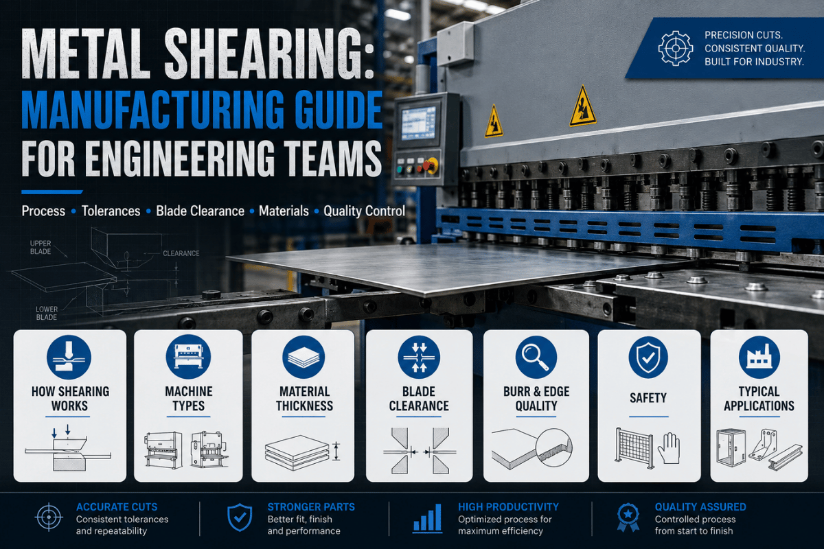
Want clean, accurate cuts through sheet metal without thermal distortion or scrap?
| Parameter | Specification |
|---|---|
| Cutting method | Mechanical blade shear — cold working, no heat, no chips |
| Ma× thickness — light-duty hydraulic | Up to ¼” (6 mm) mild steel |
| Ma× thickness — heavy-duty hydraulic | Up to 1¾” (45 mm) mild steel |
| Standard tolerance | ±0.010″–0.030″ (±0.²5–0.75 mm) |
| Back-gauge positioning | ±0.005″ (±0.13 mm) on CNC-controlled systems |
| Blade clearance — mechanical | ~7% of material thickness |
| Blade clearance — hydraulic | 7–15% of material thickness (adjustable by material) |
| Edge finish | Clean straight cut; minor burr proportional to clearance |
| Compatible materials | Mild steel, stainless steel, aluminum, copper, brass, titanium (thin gauge) |
Metal shearing is a cold-working fabrication process that cuts sheet metal, plate, or strip using two opposing cutting blades pressed past each other under high shear force. No heat is applied to the material, no material is removed, and no chips are created; producing a clean straight cut with very little burr.
This is a fast, chip free alternative to sawing, laser cutting, or plasma cutting, for straight-line work.
Named after the dominant stress mode: unlike sawing (which removes material by abrasion) or laser cutting (which melts the workpiece), shearing applies pure shear force until the metal fractures along the blade line. Because the process is entirely mechanical, there is no heat-affected zone (HAZ) — material structure and hardness remain intact right to the cut edge.
Shearing and cutting are some times confused, but mechanically they are quite different. Shearing is a matter of applying two forces in opposite directions without removing material, the edge of the workpiece localto the cut fractures off along a path. Cutting, generally speaking, covers the use of saws—which remove chips by abrasion—, laser—the reduction of work pieces by vaporization—and plasma—the destruction of the workpiece by melting and blow-away—all of which involve removal of material.
Cutting is associated with kerf-loss and thermal effects, shear is free from both of these and therefore the most efficient for straight cut work in sheet/plate materials.
Engineering Note: The blade offset (the distance between the upper and lower cutting edge measured horizontally) for all except light metals should usually be kept at 5-10% of the material thickness. The amount of clearance controls the fracture path: insuficent clearance results in the process double-shearing (the second bright zone causes rapid wear of the blades) and excess clearance results in a folding and rolling of the metal rather than shearing.
Shearing Advantages
Shearing Limitations
All shearing processes share a common sequence, whether it is a small bench shear or a 600 ton industrial hydraulic guillotine. They are:
| Material | Mechanical Shear | Hydraulic Shear | Key Risk |
|---|---|---|---|
| Mild steel | ~7% | 7–10% | Over-clearance → fold and burr |
| Stainless steel (304) | 5–7% | 7–12% | Under-clearance → work hardening, blade wear |
| Aluminum | 6–8% | 8–12% | Over-clearance → torn edge |
| Copper / Brass | 5–7% | 7–10% | Galling if clearance too tight |
| High-strength steel (HSLA) | 8–10% | 10–15% | Rapid blade wear if under-set |
In Practice:A structural steel fabricator operator loads a 3 mm mild steel sheet on the hydraulic guillotine shear. The operator checks the back gauge position 450 mm 0.5 mm and the blade gap parameter dialed in to 0.21 mm – 7% of the nominal 3 mm (11/2″) material thickness before the first cut of the day. The hydraulics activate, hold-down clamp drops, blade quickly glides down at a 3 rake, and the cut appears completed in less than 1 second. A cross section of the finished edge: 55% of the 0.055 burnish zone^ burns off in the top layer, and the remaining 45% of the zone “b uckles off into the fracture zone^! is contained within tolerances for structural sheet plate blanks. The operator straightens the subsequent cut with no adjustments needed.
The Hidden Cost of Wrong Blade Clearance: With a blade clearance variation of 2-3 percentage points above the range recommended ^— 10% instead of 7% for mild steel— the workpiece will practically crumple its way through the cut, forming a large heavy rolled burr on the finished edge. You pay the price: this convex burr can cause interference fit issues downstream, require labor intensive deburring, and even cause production batch rejection. OSHA and FMRC fabrication shop field reports have indicated that improper blade clearance is one of the most prevalent shearing quality/acceptance quality escapes, and most authors depict inspection occurring after rejections begin to increase.

Procurement Power shear^ selection is often based solely on functional choice of machine capacity to “fit” requirements, but a large hydraulic guillotine shear does not lend itself to low volume prototyping, and a small bench shear cannot hold the stock across thick plate. Use the following decision tree along with the lumped machine categories below to choose the most appropriate machine type.
| Machine Type | Max Thickness (Mild Steel) | Typical Speed | Best Application | Cost Tier |
|---|---|---|---|---|
| Hydraulic guillotine shear | 6–45 mm | 2–5 cuts/min (heavy), 6–8 (light) | High-volume plate/sheet production | $$–$$$ |
| Mechanical shear | Up to 6 mm | 6–12 cuts/min | Medium-volume sheet fabrication | $$ |
| CNC servo hydraulic shear | 6–25 mm | 4–8 cuts/min | Precision production, mixed thickness runs | $$$ |
| Bench / lever shear | Up to 10 mm (flat bar) | Manual | Small shop, rough blanking, low volume | $ |
| Electric power shear (handheld) | Up to 12 gauge (2.7 mm) | Variable | On-site cutting, large sheet blanking | $ |
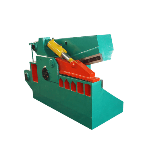
| Alligator shear | Structural sections (rebar, angle iron) | Variable | Scrap processing, demolition | $$ |
| Throatless shear | Up to 16 gauge (1.6 mm) | Manual | Curved and irregular cuts in thin sheet | $ |
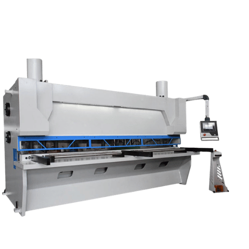
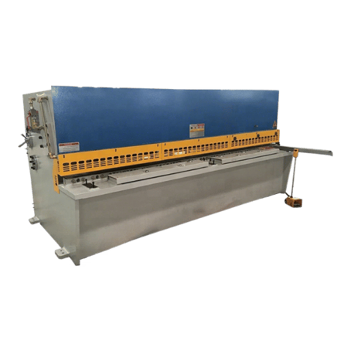
The hydraulic guillotine shear (also called a guillotine shear, squaring shear, and power shear) is the most prevalent machine category in industrial sheet metal fabrication. Commercial standard machine models feature between 1200 & 6000 mm (41.5′ & 198.0”) cutting length; larger, high productivity industrial machines can reach 8 m (~27 ft) in cutting length with sheet capacity of 45 mm thick. Hydraulic ram deformation replaces the traditional flywheel of older mechanical shears; reason the ram descends at a constant rate of speed and maintains constant tonnage across the execution of each cycle.
The diversity of shop terms: a guillotine shear, squaring shear, and power shear all refer to the same basic machine category—a powered, fixed bottom edge and threshold powered top edge shear. “Guillotine” shear is most common in European, and large scale industries; “squaring shear” is used in North American sheet shops;” “power shear” is called an electric or handheld shear when it is not machine mounted. A manual bench shear is an electrically powered, table-mounted shear.

Power shearing can be performed on any ductile metal on a normal machine provided it falls within the strip tensile strength limits for that machine. High-tensile or brittle metals must be sheared on a high tonnage machine or not at all.
| Material | Max Thickness (Mechanical) | Max Thickness (Hydraulic, Standard) | Notes |
|---|---|---|---|
| Mild steel (A36, A1011) | Up to ¼” (6 mm) | Up to ~1″ (25 mm) | Reference material for all shear ratings |
| Aluminum (6061, 5052) | Up to 3/8″ (9.5 mm) | Up to ~1¾” (45 mm) | Softer = higher capacity vs. mild steel |
| Stainless steel (304) | Up to 3/16″ (4.8 mm) | Up to ~½” (12.7 mm) | 40–50% lower capacity than mild steel equivalent |
| Copper | Up to ¼” (6 mm) | Up to 3/4″ (19 mm) | Similar to aluminum; watch for galling |
| Brass | Up to 3/16″ (4.8 mm) | Up to ½” (12.7 mm) | Work-hardens less than stainless |
| Titanium (Grade 2) | Up to 1/8″ (3.2 mm) | Up to ¼” (6 mm) | High tensile strength — demands heavy machine |
Best Meil for Shearing- Mild steel & Aluminum are the best well sheared metals; both are ductile and can be fractured easily and cleanly without the need for slack blade clearance. Copper & Brass are also easily well-sheared metals, particularly lighter gages. Stainless (304/316) can be sheared, but the higher tensile (around 700 N/mm versus around 400 N/mm for mild steel) strength of the stainless decreases the effective machine cutting power (by around 40-50%) and the inevitable tendency to work harden means the blade clearance need to be held within the tighter part of the range. See our stainless steel machining service for use in applications which otherwise require individual process entries. For aluminum blanking at higher thicknesses, see aluminum CNC machining.
Should Not Shear- Hardened tool steels, i.e. D2, H13, 4140; tungsten carbide, and brittle cast irons- all will cause chips and cracks to form at the shear blade instead of fracture. Difficult materials should be cut using wire EDM, grinding or plasma- see Wire EDM machining for accurately dimensioned, close-tolerance hard material.
Engineering Note- any material above approximately 690 MPa tensile strength (100,000 psi) requires a dedicated high-pressure shear machine or process change out. Stainless, which work-hardens under shearing, means the edge quality is compromised more by blade sharpness & clearance than with mild steel, with burr & tear comparable to or worse than abrasive grinding when the blade is dull- see our abrasive grinding service.
Shearing is a mid-precision process. It is best for achieving consistent dimensions (better than sawing) and recommended over plasma cutting; however, laser cutting tolerances are narrower and accomplish thin or intricate shapes. Investigate your tolerance needs before selecting a process and vendor.
| Process | Typical Dimensional Tolerance | Edge Finish | HAZ | Best For |
|---|---|---|---|---|
| Shearing | ±0.010″–0.030″ (±0.25–0.75 mm) | Clean straight; minor burr | None | High-volume straight cuts, plate blanking |
| Laser cutting | ±0.002″–0.010″ (±0.05–0.25 mm) | Smooth; may have striations on thick plate | Yes (thin) | Complex profiles, tight tolerances, thin gauge |
| Plasma cutting | ±0.030″–0.060″ (±0.75–1.5 mm) | Rough, dross present | Yes (significant) | Thick structural plate, low precision |
| Saw cutting | ±0.005″–0.020″ (±0.13–0.5 mm) | Smooth; chip removal required | None | Bar stock, small batches, non-sheet |
Any dimension that is not a very short cut (see table below) will likely be within industry standard tolerance (ASTM A568 / ISO 2768). Typical tolerances are as follows:0-1″ = 0.005″; 1-12″ = 0.010″; 12-24″ = 0.020″; over 24″ = 0.030″+.
Engineering Note — Burr height is directly proportional to shear clearance (the gap between upper and lower cutting blades). Correct clearance generates a small, consistent burr at the boundary of the fracture & burnish zones. Too much clearance causes a large, rolled burr due to the fold. Too little causes a double-shear burr, with a secondary bright band. When consistent edge quality matters, specify blade clearance as part of your shearing service and account for strip twist (common in very narrow strips less than 10 x the material thickness- 10-15 x is preferable).
Nominal tolerances for shearing of widths narrower than 10x the material’s thickness is a good rule of thumb to avoid twist. For better than 10x the material’s thickness, work from tolerances listed to evaluate whether the process is already up to the challenge, or a better one should be used. When tolerances tighter than 0.010″ are needed, shearing should probably be used only as a pre-process or eliminated altogether- see metal CNC machining or consult our tight tolerance machining guide. When used in conjunction with machining, sheared blanks are often CNC milled to a finished shape or dimension – see CNC milling service.

Choosing between shearing and alternative cutting processes comes down to economics — neither is universally better. Match your process to your tolerance requirement, material thickness, and production volume. This matrix illustrates all the options.
| Material Gauge | Volume | Tolerance / Profile | Recommended Process |
|---|---|---|---|
| Any gauge | Any | Curved or complex profile | Laser / Plasma / Waterjet — shearing cannot produce curves |
| <14 ga (<1.9 mm) | <10 pcs | ±0.005″ or tighter | Laser cutting |
| <¼” (6 mm) | Any | Straight cuts, ±0.010″–0.030″ | Shearing |
| 3/8″–1″ (10–25 mm) | >100/month | Straight cuts | Shearing — 36× throughput advantage over 4kW laser |
| 3/8″–1″ | Low volume | Complex profile | Plasma / Saw cutting |
| >¼” plate | Any | Straight blanks | Shearing (then CNC milling for finish) |
| Any | >10,000/month | Repeated net-shape blanks | Stamping (shearing for first-op blank only) |
For very thin gauge work (<“) where close tolerances or very curved profiles are needed, Laser is the obvious choice: it produces 0.05 mm or better and no burr on this light material. But at 3/8″ (10 mm) plate and over, a sharp drop in laser process: a four kilowatt fiber laser will go from 190200 IPM on thin gauge to 6070 IPM on 38” plate, hard. At 12 mm, a hydraulic shear can produce about 36 times an hour’s volume of straight cuts.
Shearing costs many times less to operate: Laser machines will typically cost $300K-$500K to buy and $1570 per hour to operate; a similar hydraulic shear costs on the order of $30K and a few tenths of a cent per cut. For mass production of blanked, straight cut parts in plate or heavy-gauge sheet, the calculations tip heavily.
Scenario A- HVAC Contractor (Shearing ): A sheet metal contractor fabricating galvanized duct panels requires 5,000 straight cut blanks per month in 18-gauge (1.2mm) steel to 0.020″ tolerance. All cuts are rectangular, zero curves. A mechanical shear at $28,000 completes this run in a single shift at a cost of approximately $0.002 per cut.
Laser cutting the same volume at $15/hour machine time would cost roughly 40 more per piece – and extend lead time for machine programming set up on each duct profile change.
Scenario B—Aerospace Bracket (Laser): An aerospace supplier requires 20 units of 0.125″ (3.2 mm) 6061- T6 aluminum brackets per order, with each having 0.005″ dimensional tolerance and two complex radiused cutouts. Shearing cannot create the radiused features, and even on the straight edges, the shearing tolerance of 0.010″ to 0.030″ exceeds the 0.005″ requirement. Laser would come out ahead in terms of capability and economics for these low volume brackets.
Scenario C- Automotive Door Blank (Stamping + Shearing): A Tier-2 automotive supplier makes 1.5 mm HSLA door blanks, fabricating 50K/ month. By this volume, the production method is progressive die stamping – but the line is run from coil and the first operation is a sheared blank cut to width from master coil stock. Shearing and stamping are one operation: shearing does the high-speed straight-cut prep; stamping does the net-shape forming.
Laser cutting could not keep pace with the coil-to-blank throughput rate at this level of production.

Almost all manufacturing industries utilizing flat metal make use of the metal shearing process, whether they realize it or not: HVAC ductwork, aerospace blanks, etc. The real question is not which industries shear but at what part geometric shape, tolerances, and amount of use does shearing become acceptable or not.
In a Tier-2 Stamping Plant: A 600-ton hydraulic guillotine shear blanks 1.5mm HSLA coil steel at 6 cuts/min feeding blank directly into a progressive stamping die; each blank hits on average at 0.5mm on both dimensions 23ppcm. This is well within the 1.0 ppcm incoming tolerance the die will require. Shearing at volume is roughly 80% less expensive per blank than laser cutting; the shear operator runs alone during each shift, three operators would be needed for the three laser-cutting stations to run throughput at this speed. This is why shearing is still the first operation in the vast majority of automotive sheet metal fabrication shops.
Not every shearing shop can hold the tolerances your part requires. Ask your shearing service these eight questions before you buy sheared blanks for your application. Their answers will quickly weed out shops whose processes are not in control from shops that would prefer you not inspect:
Lecreator offers CNC machining services with sheet metal shearing (including CNC back-gauge positioning), material certification, & secondary operations. Please upload a CAD drawing for a quote with attached material certifications.

3 trends are aligning to change how shearing capacity and performance are viewed by manufacturers in 2025 and forward.
1. Servohydraulic Systems- more precise and far more energy efficient: Automotive manufacturers have already replaced old-style constant power hydraulics with servomotor driven systems that only use power when moving to set blade gap. Instead of wasting energy heating oil and then cooling it, modern servo hydraulic blades descend on programmed profiles which reduce vibration to thin gauge material. Modern servo-hydraulic shearing machines, as well as forming presses 60-70% less energy when compared to traditional hydraulic equipment and that translates to significantly reduced operating costs for high volume shops.
2. CNC Back-Gauge Automation – cuts human error: CNC controlled back-gauge set-ups displace the variable accuracy introduced by operators with manual stops, especially on multi-dimension series runs. CNC machinery utilization in North American shops was up 7% from 2022 to 2023 according to the Association for Manufacturing Technology. If your production is repetitive blanking of precision features, specify that the shearing shop is set up with a CNC back-gauge – this is the best way to measure consistency within a run.
3. Capacity investments driven by EV demand: Models of electric vehicles use a higher proportion of high strength low alloy steels and aluminum blanks than conventional internal combustion powered counterparts. These are metals where shearing remains the primary first operation. The North American press brake and shearing market hit $2.2 billion USD in 2024 and is projected to grow at 6% Compound Annual Growth (CAGR) through to 2034 to an estimated $3.9 billion. For purchasing influences, therefore, this equates to continuous capital purchase of new shearing capacity from Tier-1 and Tier-2 equipment suppliers; these newer servo-hydraulics provide more precision than older mechanical lines.
Call to action. If you are purchasing shearing equipment for aerospace, automotive, or electronics applications, specifically request that your available supplier confirm regular blade maintenance cycles and be able to provide an example of blade wear monitoring. These factors have the most dramatic effect on edge quality and dimensional consistency throughout a production run of any order.
Shearing is a cold works fabrication process by which sheet metal is cut with a force applied to two blades pressing past each other. In five-finger terminology, no heat, no chips, and no material exfoliation occurs – the metal breaks along a clean fracture line. It is the most time-efficient and cost-effective technique for a straight line cut in sheet and plate metal where turn-around speed is paramount.
Mild steel (A36, A1011) and aluminum (6061, 5052) are the most commonly sheared metals since they are ductile and moderate tensile strength. Copper and brass blades shear up well at a standard range of gauges. Stainless steel (304/316/301 etc.) has a higher 40-50% capacity demand to shear and must be cut with tighter tolerances on out-flank clearance. The work hardening properties in ductile steels and titanium alloys will out-fracture plain blade edge. Hardened tool steel, tungsten carbide and brittle materials like cast iron will chip out blade edges rather than produce a clean fracture.
In shearing, the two sides of a straight blade apply opposing normal compressive forces causing a fracture at the shear line – no material is removed in process, and no heat is generated. Shearing is one subsection of cut using, the other types including sawing (chip removal via abrasive action), laser (vaporization), and plasma (extremely high-power arc, blasting molten material out). Shearing produces zero kerf loss, and retains most of the original material properties to the shear cut edge.
Industry and country variations often describe blade shearing machines as guillotine shears, squaring shears, or power shears – all have the same basic machine type. “Guillotine shear” is common to Germany and continental European heavy industry. “Bench shear” or “lever shear” is used to refer to non-powered shear blades on small, bench-mounted units for light gauge work. Electric handheld shear units are called power shears for generic usage, or tin snips if used on light gauge material.
Cut capacity in thickness of material depends solely on the machine type and material type. Mild steel usually ranges from 3/16″ (5 mm) on small hydraulic cutters, up to 1″ (25 mm) on brute-force hydraulic guillotines; stainless steel 40-50% less on the same machine. 100% service factor is minimal for a shear rated for your required application. Please check your material grade when quoting shearing services, not just steel.
Zero taper, 0.010″-0.030″ (0.25-0.75 mm) standard tolerance on shearing depending on cut length – short run parts require tighter tolerances. CNC back-gauge positioning down to 0.13 mm (0.005″) reduces part-to-part error significantly compared to gauge stops. Tolerances tighter than 0.010″ must be laser cut or CNC machined.
Yes, stainless steel shear is possible, but expect ~50% higher capacity recommendation versus mild steel of equal thickness, because of the higher tensile strength and work hardening tendency. Blade gaps must be reduced for the same reason, at the lower end of the recommended range to prevent work hardening at the cut edge.
Blade to material gap (or “clearance”) is set as a percentage of stock thickness. Typical for mechanical shear units is 7%. The hydraulic shears use a 7-15% range, where harder materials such as stainless or high-strength steel tend to push the optimal percentage to the 15% range to allow clean fracture. Too small a clearance produces rapid blade dulling and double-shear burr; too large a gap produces the work piece curling excessively and the formation of a large rolled burr.
About This Guide
This sheet metal shearing technology guide is based on OEM machinery specifications (Cincinnati Incorporated, Ursviken), on engineering standards adopted by the industry for fabrication (ASTM A568, ISO 2768) and market research (Global Market insights, Association for Manufacturing Technology), or on information gathered through practitioner forums (PracticalMachinist.com) and recommended industry standard references (Degarmo, Black &Kohser, Materials and Processes in Manufacturing). Length and sheet stock thickness tolerances ranges reflect typical values used in industry – actual results vary depending on machine specific model, actual blade life and condition, grade of material used as well as machine setup performed by operating personel. Check with your shearing service provider to confirm suitability of operation.