

Supportive, Professional, Client-Focused Service
From prototypes to full-scale production, we’ve got you covered.


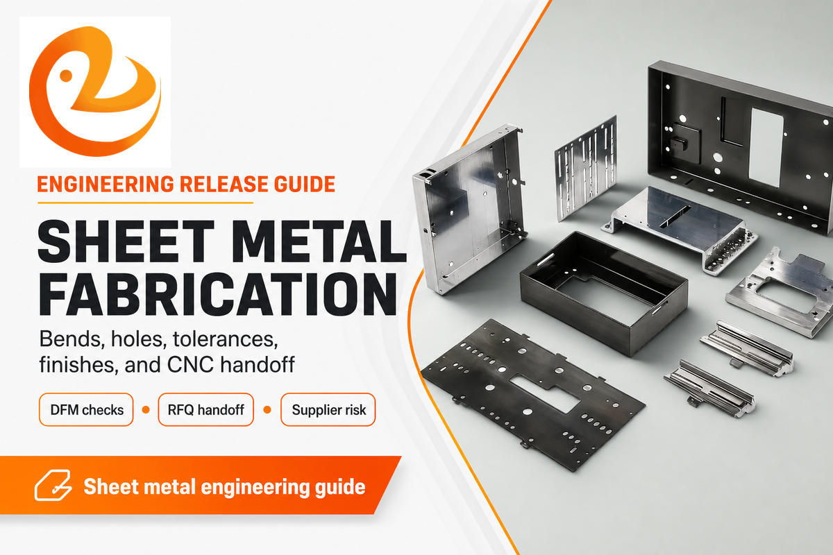
A sheet metal fabrication guide is a pre-release engineering checklist for deciding material, thickness, bend strategy, hole and slot geometry, tolerance intent, finish, inspection points, and supplier handoff before the RFQ leaves engineering. It is not a substitute for a fabricator’s tooling rules; it helps teams expose manufacturing risks early enough to act.
Use this guide as a pre-release review for enclosures, brackets, frames, covers, panels, electrical housings, fixtures, and precision sheet metal components. Lecreator’s sheet metal fabrication services page gives the service context for teams comparing design options.
Fast decision flow: confirm the sheet metal part function, choose material and sheet thickness, define bends and reliefs, check holes and cutouts near bends, separate critical dimensions from general dimensions, choose finish and hardware, then send a CAD file and drawing package with revision control.
Engineering release should answer the manufacturing risk question before the RFQ: which features are sheet-metal work, which features need machining, and which dimensions deserve inspection discipline?
The guide covers material selection, sheet thickness, bend design, feature spacing, tolerance strategy, finish, hardware, RFQ handoff, and supplier risk controls before drawings reach a fabrication shop. It gives engineering teams a manufacturing release checklist rather than a generic process overview.
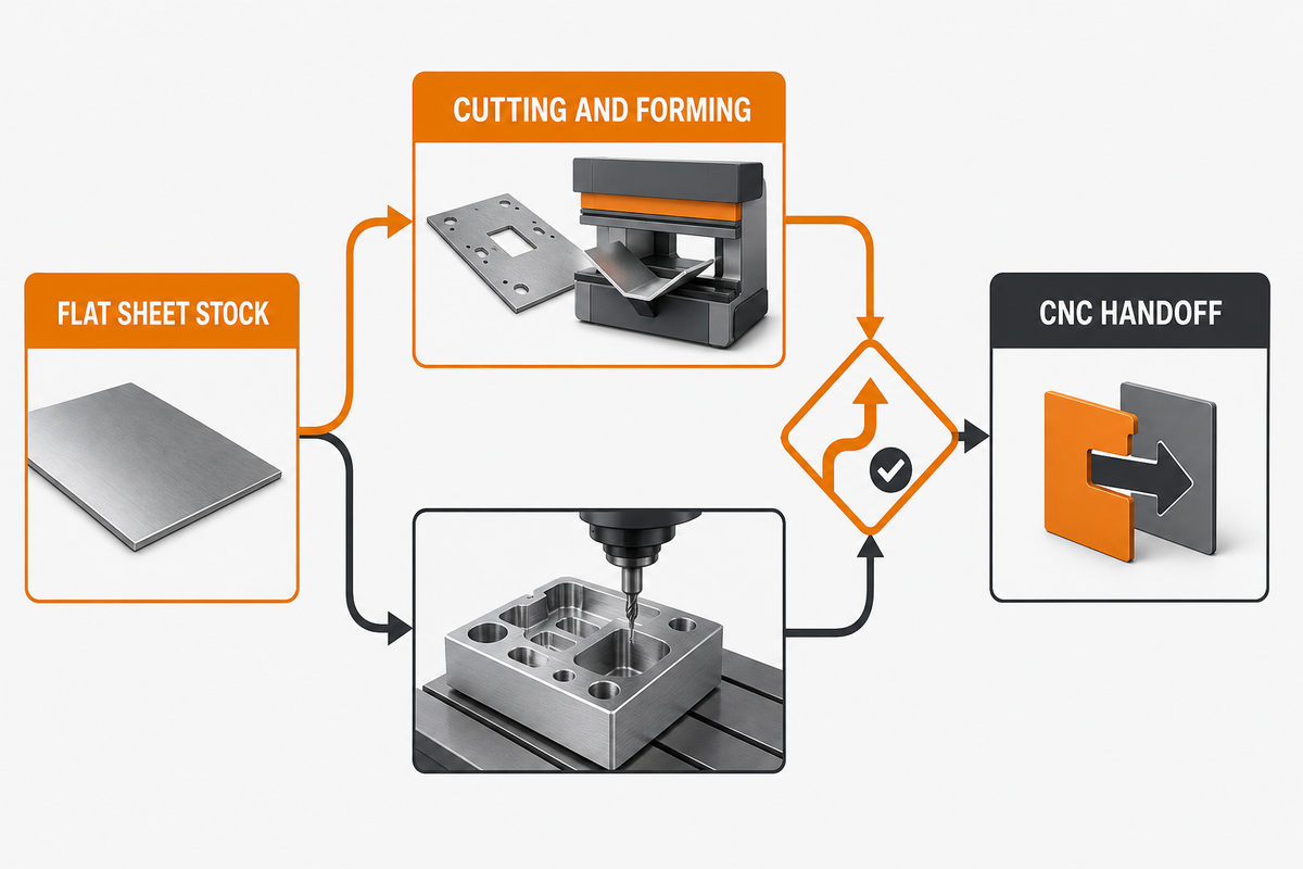
Sheet metal fabrication usually starts with flat sheet stock and turns it into metal parts through cutting, punching, bending, forming, joining, finishing, and inspection. CNC machining removes material from a block, bar, plate, or near-net blank. That difference matters when a feature needs a thick boss, a flat sealing land, a precise bore, or tight thread alignment. In those cases, the right answer may be a hybrid design instead of forcing every feature into one sheet.
For engineering release, treat this guide as a risk checklist. It does not replace the fabricator’s own tooling rules, material data, or inspection plan. It gives the team a common language before the shop reviews the file.
For teams that want a practical introduction to sheet metal fabrication, the core idea is simple: a single sheet of metal, sometimes called a metal sheet or sheet material, is cut and formed into a piece of sheet metal with controlled bends, holes, hems, corners, hardware, and finish. The advantages of sheet metal include low material waste, repeatable forming, and fast enclosure work; the advantages of sheet metal fabrication depend on matching the design process to the right types of metal and production route.
Important design considerations include base metal selection, sheet metal materials, design specifications, tolerances for sheet metal fabrication, and the order of the cutting process, sheet metal bending, sheet metal forming, and assembly. These best practices help engineers design sheet metal parts for various sheet metal components, precision sheet metal fabrication work, and real metal fabrication projects without losing the original design intent.
Use these design tips as a vocabulary check, not as a substitute for shop review: holes in sheet metal need spacing review, sheet metal hems need forming access, corners of sheet metal need relief and radius checks, and a finished sheet metal product should be judged against function, appearance, and inspection requirements. This is the practical meaning of design for sheet metal and sheet metal design for manufacturability.
Other terms may appear during supplier review: aluminium, copper, brass, plasma cutting, stamping, blanking and piercing, punch press, machine tool, die, workpiece, tonnage, computer-aided design, and computer numerical control. Each term can change the base metal choice, tooling path, or inspection plan.
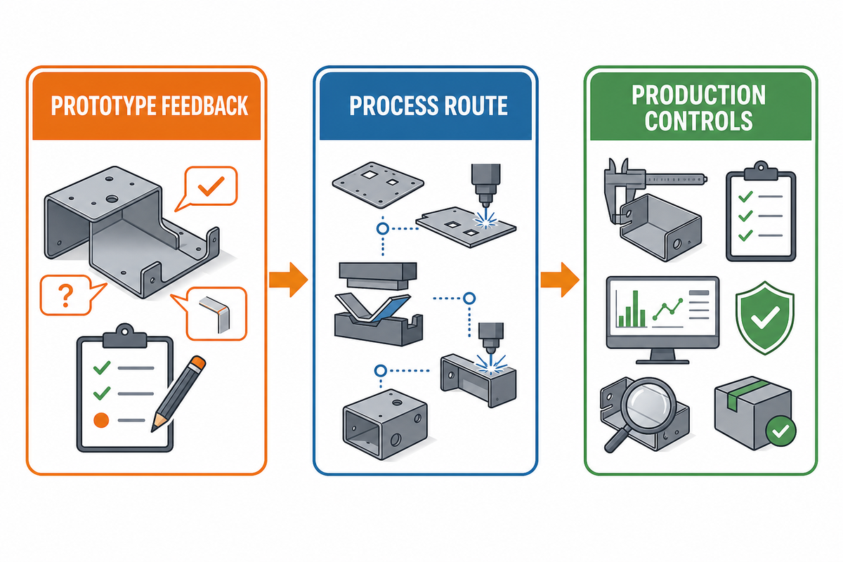
In practice, the sheet metal fabrication process route normally goes like this:
| Step | Engineering decision | Common risk if missed |
|---|---|---|
| Material release | Grade, temper, thickness, grain direction, coating | Wrong bend behavior, finish mismatch, corrosion issue |
| Blanking or cutting | Laser, punch, shear, waterjet, or saw route | Burrs, heat marks, poor small-hole quality |
| Forming | Bend radius, bend sequence, relief, flange length | Distorted features, trapped tooling, cracked bends |
| Joining | Welds, rivets, clinch nuts, inserts, tabs, slots | Warp, weak joints, blocked hardware access |
| Finishing | Powder coating, anodizing, plating, brushing, masking | Thread contamination, cosmetic rejects, coating buildup |
| Inspection | Critical dimensions, fixtures, datums, sample approval | Parts that pass a drawing but fail assembly |
Prototype batches often favor lower setup burden and fast drawing feedback. Production batches may justify dedicated tooling, tighter process windows, fixtures, and more formal inspection steps. A rapid prototyping service context can help teams test fit before production tooling. Do not choose the route by unit price alone. That cheap first batch can become costly if the manufacturing process cannot repeat the same bend sequence, finish quality, or assembly fit.
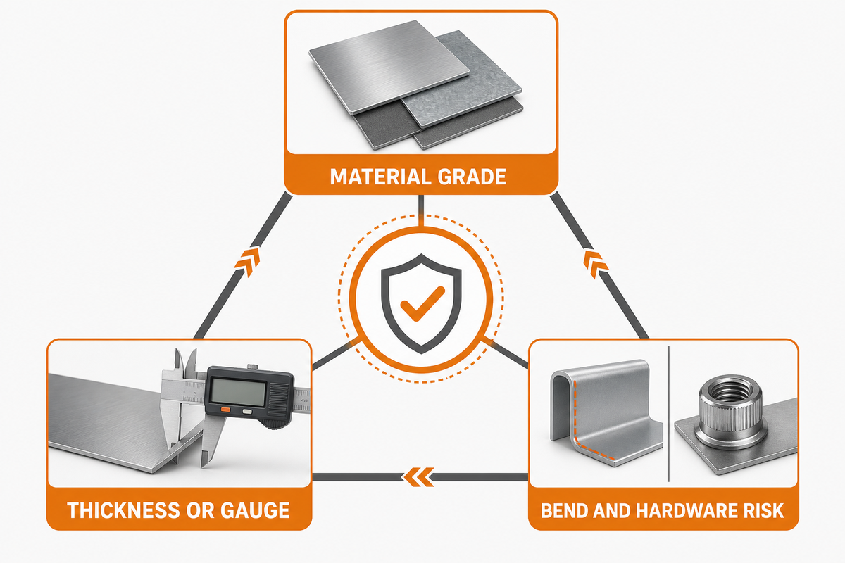
Material choice sets the limits for bend radii, edge quality, welding, coating, weight, and corrosion resistance. Aluminum is light and forms well in many alloys, but surface marks and bend cracking must be reviewed by alloy and temper. Stainless steel offers corrosion resistance and strength, but it can demand more forming force and careful finish handling. Mild steel and carbon steel are cost-friendly choices for brackets and frames, while galvanized or pre-coated stock may reduce later finishing steps but adds coating damage concerns at cuts and bends.
Sheet thickness affects more than strength. Thicker sheet usually needs more bend force, larger tooling, larger minimum flanges, and wider reliefs. Thin sheet may save weight, but it can flex, oil-can, or distort around hardware. When the drawing calls a sheet metal thickness range, the team should confirm which value drives the flat pattern, weight target, stiffness, and hardware selection.
For risk review, treat a 1.0 mm gauge change as a manufacturing decision because it can shift bend force, hardware grip, and flat-pattern assumptions. Ask for material certification, CNC metal machining insert planning, and precision inspection notes when the material choice affects assembly fit.
Good material notes answer these points:
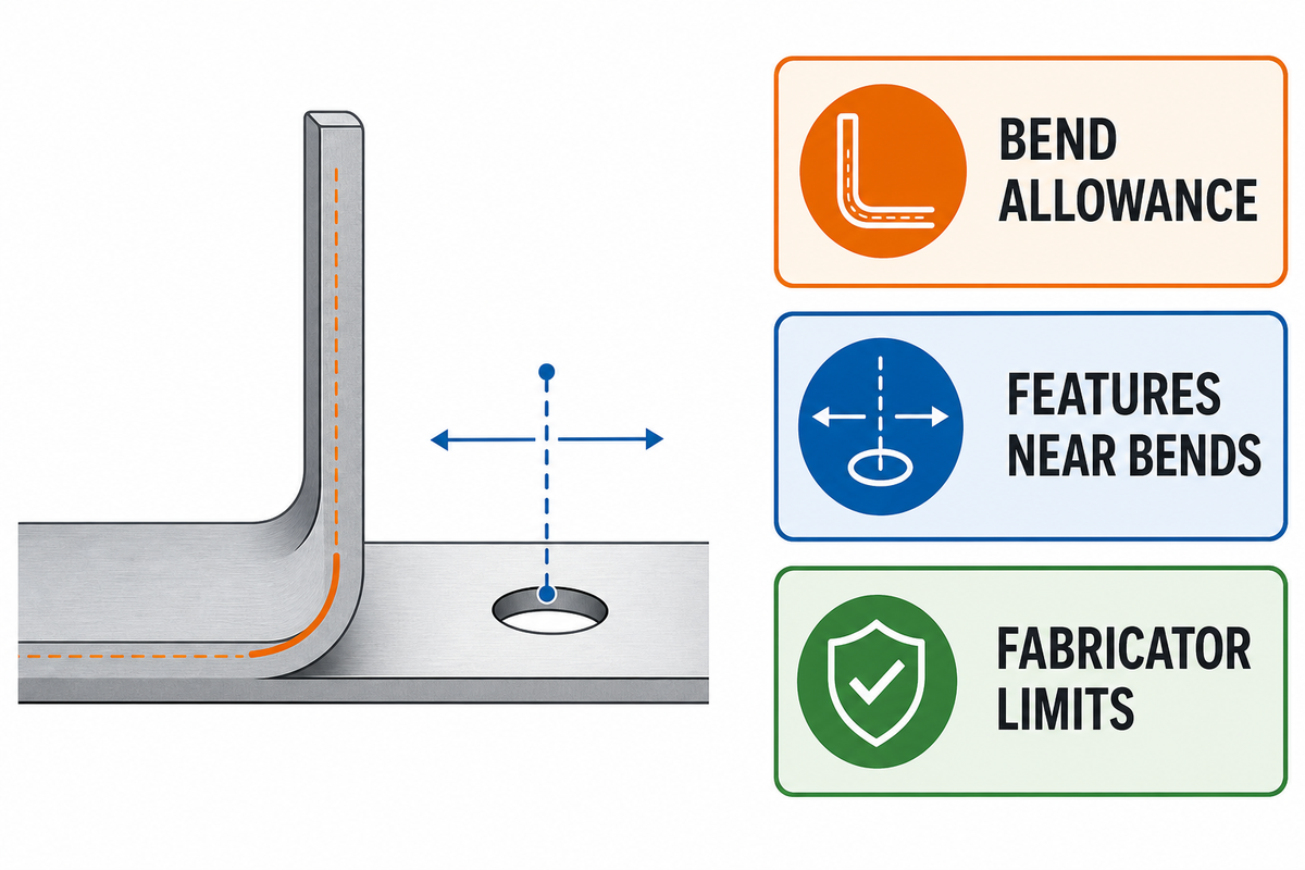
Bending is where many sheet metal design failures begin. During a bend, the outside surface stretches and the inside surface compresses. The neutral axis shifts through the material, and the K-factor helps estimate how the flat sheet should be developed before forming. In practice, K-factor, bend allowance, and bend deduction depend on material thickness, inside bend radius, tooling, bend method, and shop data.
That is why generic rules should be treated as planning checks. Flange length near four times material thickness, hole distance several thicknesses away from a bend, or inside radius near material thickness can be useful review triggers. A university-hosted sheet metal design guide is useful as training context, but these rules are not universal acceptance rules. Fabricators may approve tighter features with the right die, sequence, or material, or reject a generous-looking feature because the tool cannot reach it.
| Bend review item | What to check | Why it matters |
|---|---|---|
| Inside bend radius | Compare radius with material, thickness, temper, and tool opening. | Too tight can crack; too large can change fit and appearance. |
| Minimum flange | Confirm the flange can sit against the die and be held during bending. | Short flanges can slip, deform, or require special tooling. |
| Bend relief | Add reliefs where edges, tabs, or adjacent bends would tear. | Reliefs reduce tearing and uncontrolled material bunching. |
| Bend sequence | Check whether later bends trap the part or collide with tooling. | Geometry that unfolds in CAD may still be impossible to form. |
Holes, slots, louvers, countersinks, embosses, and tabs near a bend line can distort during forming. Use bend-proximity guidance as an early warning, then ask the fabricator to confirm the actual limit for the material and press brake setup. If the feature must stay close to the bend, consider moving it after forming, changing the bend sequence, adding relief, or redesigning the interface. Flag datum holes so inspection does not treat a cosmetic cutout and a locating feature as equal risks.
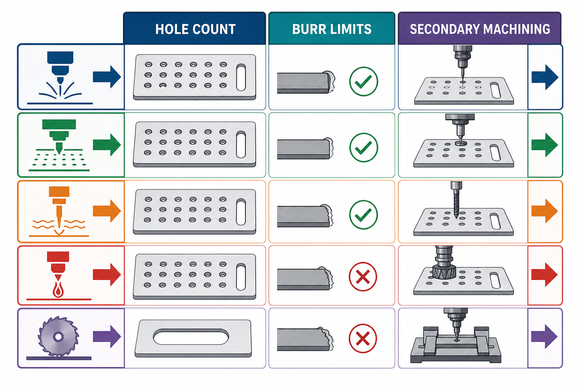
Laser cutting is a strong option for many sheet metal features, but “laser-cuttable” is not the same as “best manufacturing route.” Small holes, narrow slots, close edge distances, and holes through formed faces deserve process review. Depending on hole count, aspect ratio, taper allowance, heat-affected zone limits, burr limits, and acceptance criteria, the answer may still be laser processing, punching, drilling, secondary machining, or a design change.
Before release, check these feature groups:
A simple feature can become expensive when it forces a second setup. For example, a bracket with one tight round bore may be cheaper and more reliable as a sheet-metal body plus a machined insert than as an all-sheet design with repeated rework. In contrast, a dense pattern of small holes may stay with a specialized laser or punch route if the supplier can prove the feature quality.
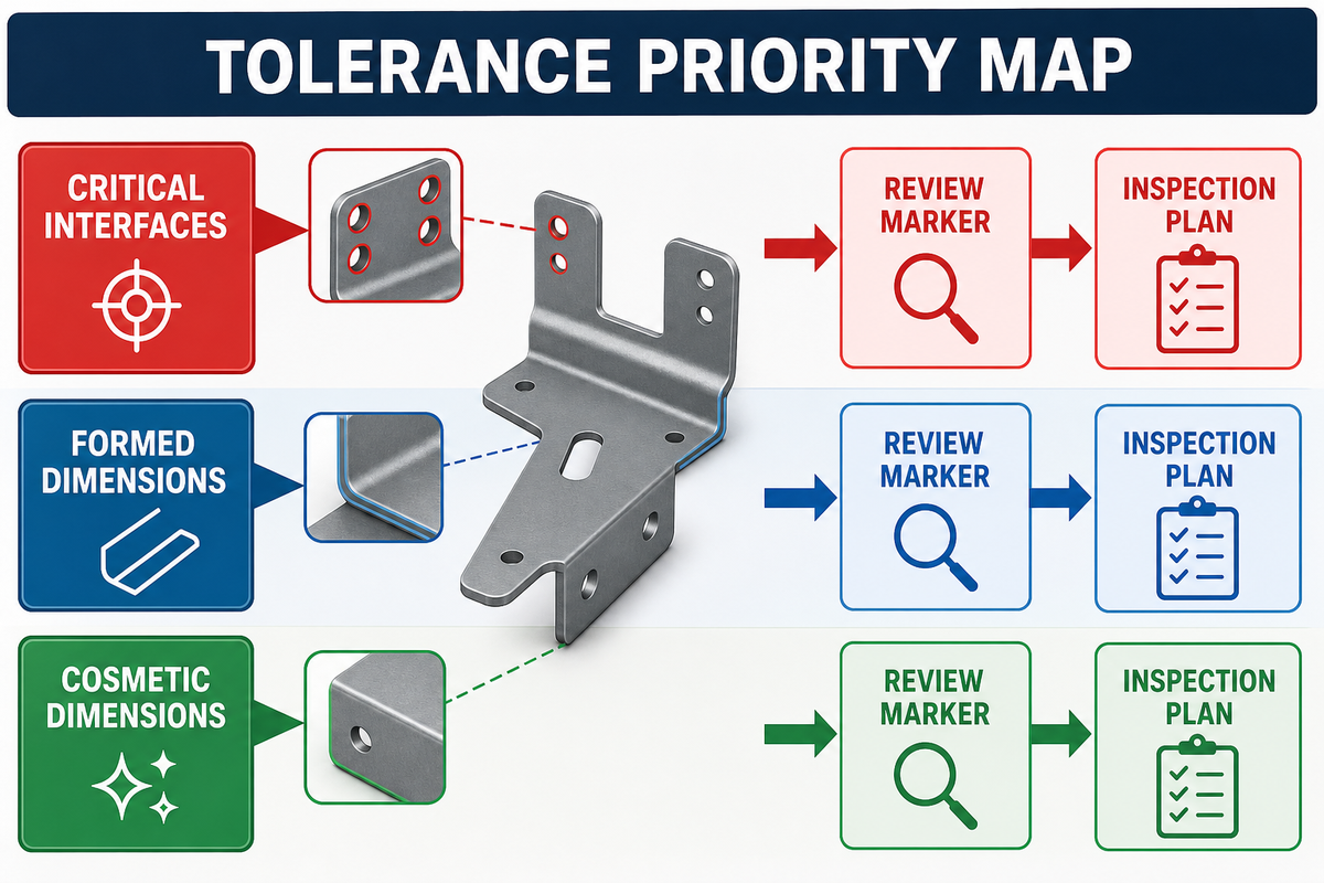
Sheet metal drawings need a tolerance strategy, not just a title-block tolerance. A flat laser-cut edge, a formed flange, a multi-bend stack-up, a cosmetic face, and a hardware location do not carry the same process risk. NIST research on dimensional measurement equipment in inspection planning is a useful reminder that process uncertainty should be shared with collaborators and suppliers. If a program invokes formal GD&T, thermal-cut quality, or customer product-definition standards, those documents control the acceptance language; this guide only helps engineering teams prepare the manufacturing conversation.
Group dimensions by function:
Use the loosest tolerance that still protects function, then call out critical dimensions clearly. Ask the fabricator for their standard tolerance table before tightening a whole drawing. Tightening every dimension can raise cost without improving the part, and it can hide the few dimensions that truly need inspection discipline.
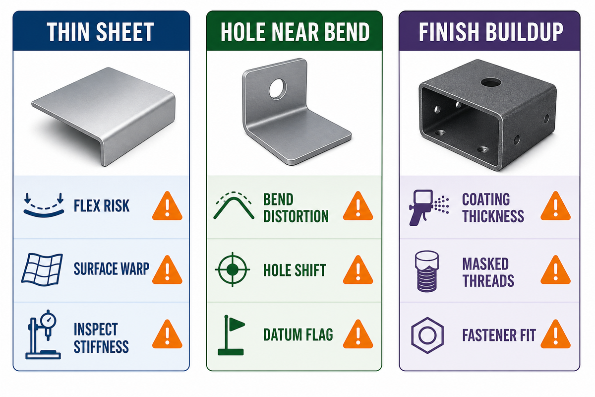
The review triggers below are examples for engineering discussion, not universal shop limits. Replace them with supplier-approved values before release.
| Risk type | Example-only review trigger | What to ask before release |
|---|---|---|
| Thin sheet | 0.5 mm to 1 mm stock | Can the part stay flat after cutting, handling, and coating? |
| Thermal cut edge | 3 mm plate or 32 mm laser-cut boundary when a standard is invoked | Which edge-quality class and inspection method apply? |
| Short flange | 6 mm to 8 mm flange on a small bracket | Can the press brake hold it without slip or tooling marks? |
| Bend angle | 90° form with a ±1° functional requirement | Is the tolerance tied to assembly fit or only appearance? |
| Hole near bend | 10 mm hole center near a bend line | Will forming distort the hole, slot, or countersink? |
| Hardware clearance | 25 mm tool-access zone around a clinch nut or insert | Can the insertion tool reach after all bends are formed? |
| Finish buildup | 5% clearance margin in a coated slot or tab fit | Should holes, threads, or grounding faces be masked? |
| Inspection timing | 2 hours for first-piece review on a new revision | Who signs off before the batch continues? |
| Packaging risk | 24 hours between finish cure and shipment | Can the cosmetic face be protected during packing and transit? |
Use clear units in drawing notes. Example-only formats include 0.5 mm stock, 1.0 mm clearance, 1.5 mm relief radius, 2 mm edge break, 3 mm plate, 5 mm slot width, 10 mm hole spacing, 25 mm hardware access, 45° chamfer, 90° bend, 5% clearance allowance, and 24 hours coating cure time when the supplier confirms those notes.
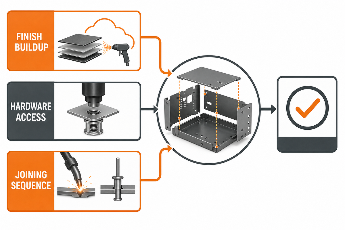
Finish and hardware should be decided before the drawing is released, not after the first quote. Powder coating can add thickness around holes and tabs. Anodizing can change cosmetic expectations. Plating can affect threads and conductivity. Brushed or grained surfaces need face direction and handling notes. Welding can add heat distortion, while rivets, clinch hardware, and inserts need hole preparation and access.
Joining decisions should follow the part’s service load, production volume, repair needs, and cosmetic requirement. Welded seams may be strong but need post-weld finishing. Rivets and screws can aid serviceability but add hardware control. Tabs and slots can help assembly alignment but must be checked for tolerance stack-up and coating buildup.
For assemblies, mark the cosmetic face, no-touch zones, masked threads, grounding points, and packaging needs. Even a dimensionally correct part can fail if a visible face is scratched or a powder-coated hole no longer accepts a fastener.
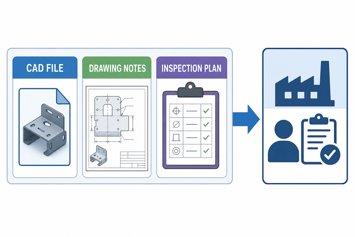
The RFQ package should let a fabricator quote the real part, not guess the design intent. Complete handoff also helps purchasing compare suppliers on the same basis, while a 3D printing service can support early prototype conversations before sheet-metal tooling is fixed.
| RFQ item | What to send | Why it matters |
|---|---|---|
| 3D CAD file | STEP or native model, with flat pattern if controlled by engineering. | Gives the shop geometry, bend intent, and assembly context. |
| 2D drawing | Material, thickness, datums, tolerances, finish, revision, notes. | Defines what must be inspected and shipped. |
| Bend notes | Inside radius, critical angles, bend relief, grain direction. | Reduces flat-pattern and tooling assumptions. |
| Hardware | Part numbers, alternates, installation side, torque or pull-out needs. | Prevents late hole-size and access changes. |
| Finish | Color, texture, standard, masking, cosmetic class, exposed faces. | Controls coating buildup and appearance. |
| Quality plan | First article needs, COC, sample approval, inspection report, packaging. | Aligns supplier work with assembly and customer risk. |
| Commercial context | Prototype quantity, annual volume, target lead time, release date. | Helps the shop choose prototype or production methods. |
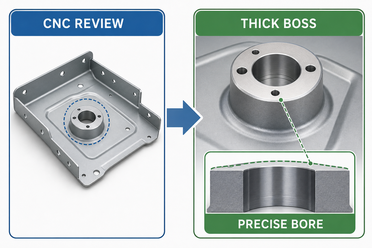
Some design requirements belong in sheet metal. Others should move to machining or a hybrid route. Hand off to CNC review when the part needs a thick boss, precise circular bore, sealing surface, deep threaded feature, tight perpendicularity, datum-critical flatness, or a rigid block-like interface. The same applies when a formed part needs a fixture, machined insert, spacer, or secondary operation to protect assembly fit.
The risk is rework: a 10 mm bore, threaded insert, or sealing face can fail inspection because forming cannot hold those interfaces repeatably. Keep those features in a CNC, machined, precision-controlled review path before the sheet-metal drawing is frozen.
For hybrid projects, review the interface early: how the machined part attaches to the sheet, where tolerance stack-up lands, whether finish happens before or after assembly, and which supplier owns final inspection. Lecreator’s CNC machining service context is useful when an engineering team needs to compare sheet-metal features against machined bosses, tight holes, and secondary operations during DFM review.
The best manufacturing process is often the one that lets each feature live in the process that controls it most repeatably.
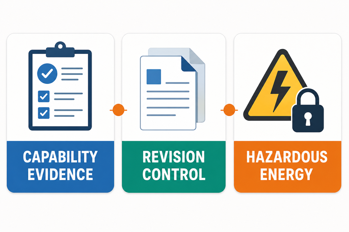
Supplier audits should confirm more than machine count. Ask how the shop reviews flat patterns, stores bend data, controls revision changes, handles first-piece approval, labels material, protects cosmetic faces, and separates prototype work from repeat production. Ask what happens when an operator finds a bend conflict or a feature that cannot be made as drawn.
For quality planning, agree on sample approval, incoming material checks, first-piece inspection, in-process checks, final inspection, packaging, and nonconformance handling. For safety-sensitive shop visits or maintenance-adjacent reviews, include hazardous-energy awareness in the audit conversation. OSHA guidance on control of hazardous energy is a useful safety reference for servicing and maintenance contexts, not a general supplier-quality audit standard. This article is not legal advice or a substitute for qualified safety training.
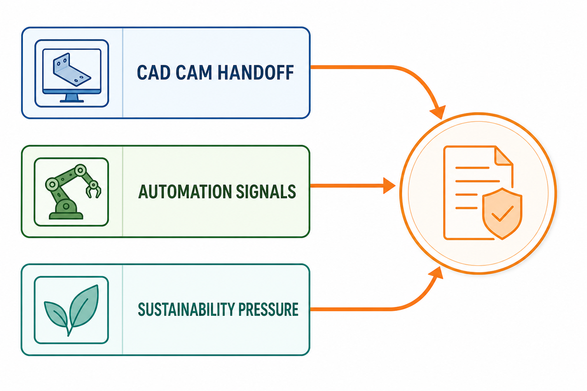
Recent fabrication coverage points toward tighter CAD/CAM handoff, fiber laser capacity, automation, advanced forming, smaller production batches, and sustainability pressure. Treat those as practice signals, not as market-size or growth-rate claims. For engineering teams, the practical lesson is simple: cleaner digital release data now matters more than ever. Even a vague drawing can move quickly through a quoting portal, but it will still fail when the bend sequence, hardware, finish, or inspection plan is unclear.
Three trends deserve attention:
Patent literature around precision bending also shows continued experimentation with ways to control bend behavior. Treat that as technology context, not as a claim that any supplier uses a specific patented method.
There is no single best material. Aluminum suits lightweight panels and some enclosures; stainless steel suits corrosion-resistant parts; mild steel often fits brackets and structural covers. Choose by strength, bend behavior, corrosion, finish, weight, cost, and whether the supplier has proven data for the sheet thickness. For critical parts, ask for material certificates and first-piece feedback.
No. Laser cutting is valuable, but small holes, tight slots, formed-face features, and high-precision bores may need punching, drilling, machining, or design revision. The right route depends on sheet thickness, feature size, tolerance, burr limits, and access after bending or coating.
Keep sensitive holes and slots away from bend lines, add reliefs where material would tear, avoid very short flanges without shop approval, and ask the supplier to confirm bend sequence. For critical parts, request a sample or first article before releasing production quantity. Review the first formed sample for hole shift, flange angle, surface marking, hardware access, and any mismatch between flat-pattern expectations and formed-part reality before freezing the batch route.
Send a 3D CAD file, a 2D drawing, material and thickness notes, finish requirements, hardware callouts, weld symbols, tolerance notes, critical inspection points, target quantity, packaging needs, and revision status. Include assembly context when fit-up matters so each supplier prices the same scope.
Use machining for thick bosses, tight bores, precise threads, sealing faces, tight flatness, and datum-critical interfaces that sheet forming cannot hold repeatably. Many products use both: a formed sheet body plus machined inserts, spacers, fixtures, or secondary features when inspection control matters.