Supportive, Professional, Client-Focused Service
Get in touch with Lecreator Company
From prototypes to full-scale production, we’ve got you covered.


Sheet Metal Fabrication: The Engineer’s Guide to Processes, Materials, and Design
| Typical Thickness | 0.5 mm – 6.0 mm |
| Common Materials | Aluminum (5052, 6061), Stainless Steel (304, 316L), Carbon Steel (SPCC), Copper, Brass |
| Key Processes | Laser Cutting, Press Brake Bending, TIG/MIG Welding, CNC Punching |
| Standard Tolerances | ±0.05 mm (laser cut), ±0.25 mm (single bend) per ISO 2768-mK |
| Typical Lead Time | 5 – 15 business days (prototype to low-volume) |
| Surface Finishes | Powder Coating, Anodizing, Zinc Plating, Brushing, Passivation |
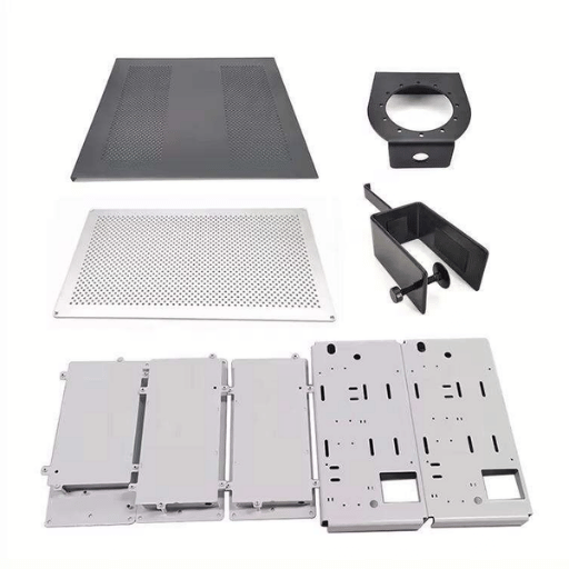
Sheet metal fabrication involves taking flat sheets of metal – 0.5 mm to 6.0 mm thick – and transforming them into finished parts. Flat stock is cut (profiled), formed (bended, stamped, drawn), and assembled (welded, riveted, fastened) into the final component. It has applications in the automotive, aerospace, electronics, and construction industries – anywhere lightweight yet strong metal sheet components are required. The global sheet metal manufacturing services market size was valued at $22.32 billion in 2025 and is forecast to grow at a CAGR of 4.55% between 2025 to 2034 to reach $33.31 billion.
This sheet metal guide covers the core fabrication processes, material selection criteria, design for manufacturability rules, cost drivers, and finishing options that engineers and procurement teams need to specify custom sheet metal parts correctly.

Sheet metal fabrication stands apart from other manufacturing options as a lean, close-tolerance process that minimizes material waste. It is fast, accurate, and material efficient — adopted in automotive, aerospace, electronics, and construction. According to Precedence Research, the global sheet metal fabrication services market reached $22.32 billion in 2025 and is forecast to grow at a CAGR of 4.55% to reach $33.31 billion by 2034.
Sheet metal fabrication uses flat stock — usually between 0.5 mm and 6.0 mm thick — and shapes it into finished components. This makes it different from other manufacturing processes such as casting or CNC machining, which respectively cast molten metal in a mold or machine material down from a large block.
Sheet metal fabrication works with a broad number of non-ferrous and ferrous materials, from aluminum to titanium. Every part fabrication begins as flat stock, which is cut using a 2D profile then transformed into the final 3D shape by a combination of bending, stamping or drawing. Multiple sheets are joined using a range of techniques, including fasteners, welds or rivets.

What sets the process apart is that it produces very little waste – a significant advantage where costs are driven by scrap material. In addition – unlike additive manufacturing processes – sheet metal fabricated parts can be recycled without suffering property degradation. Precision, speed, and material efficiency make sheet metal fabrication a staple in industries from medical enclosures to EV battery trays.
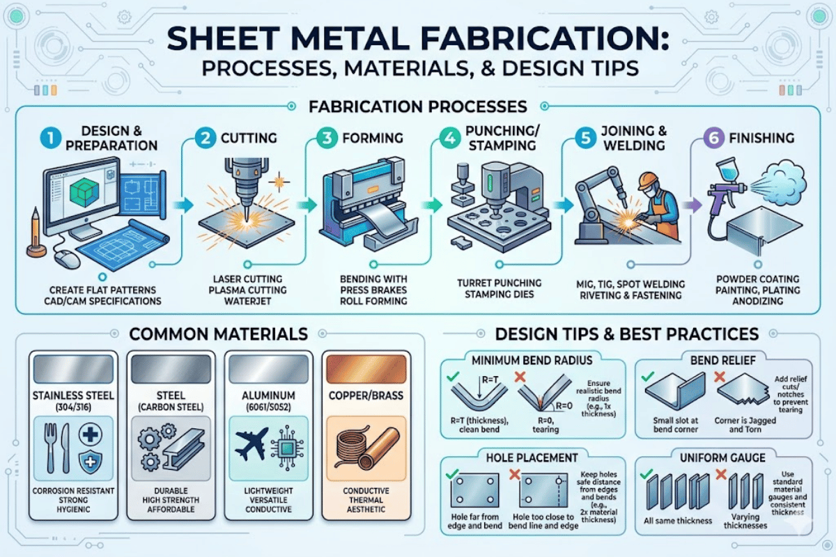
Every sheet metal fabrication process falls into one of three categories: cutting the metal sheet to shape, forming it into a 3D geometry, or joining separate sheet parts using welding or mechanical fasteners. Your choice of process determines the speed, tolerance, and cost of the finished item.
| Method | Tolerance | Max Thickness | Speed | Best For |
|---|---|---|---|---|
| Laser Cutting | ±0.05 mm | 19 mm (steel) | 10–25 m/min | Intricate profiles, thin-to-medium gauge |
| Plasma Cutting | ±0.5 – 1.5 mm | 38 – 100 mm | 2–8 m/min | Thick plate, structural steel |
| Waterjet | ±0.1 mm | 300 mm | 0.5–2 m/min | Heat-sensitive materials, reflective metals |
| Shearing | ±0.25 mm | 6 mm | Fastest (straight cuts) | Straight-line blanking, high volume |
Cutting and bending operations dominate most sheet metal fabrication work. Laser cut profiles account for the majority of production parts in precision sheet metal fabrication shops.
Following cutting, the sheet metals are raised into 3D shape. A press brake is the most versatile sheet metal bending process: a punch and die set applies force to form sheet metal, forcing it into a V-shape at a well-controlled angle. Roll forming pulls a sheet through a series of rollers to make continuous profile shapes like channels or angles. Stamping is a high-volume process where a punch press drives a part into a shape against a fixed die using a progressive set of cavities: production rates are often over 100 parts per minute. Deep drawing pulls a sheet shape across a die-form tool: the mechanical stretch pushes the sheet into a hollow cup- or box-shaped product. Enclosures, hoods, and electronic housings are typical sheet metal components made by deep drawing.
📐 Engineering Note
For sheet metal bending, minimum bend radius varies by material: using 2 the stock thickness (2 T) with a squeeze of 10% is a good practice guiding principle for aluminum; 0.8 T for mild steel, and stainless steel (1.5 T-4 T, from grade and part shape). Bending across the grain direction is a safety consideration: a bend cannot be made along the grain direction without cracking. Aluminum alloy parts have the highest need to bend across the grain, stainless steel the lowest. Bending from the grain will risk a crack, especially in hardened alloys.
Joining together sheet metal parts into an assembly is achieved with a wide set of bonding techniques. The three most common for metals are GMAW (Gas Metal Arc Welding, also known as MIG welding), GTAW (Gas Tungsten Arc Welding, a.k.a. TIG welding), and Resistance Spot Welding. GMAW is the fastest approach for carbon steel and alloys like aluminum: it draws a continuously fed wire through a gas-shielded gun, melting the wire into the weld pool. GTAW makes cleaner, more precise welds but at lower feed rates than GMAW: it inserts a tungsten electrode into the weld pool. Spot welding is a low-heat method where two sheets are pressed together at discrete locations and resistance heats the areas between the sheets. For non-permanent joints, metal fabricators use rivets and mechanical fasteners such as PEM inserts that allow disassembly and service access.
Choosing the right sheet metal materials starts with three factors: mechanical load, operating environment, and cost. Below is a summary of common choices for the typical mechanical properties that impact fabrication.
| Material / Grade | Tensile Strength | Density | Corrosion Resistance | Relative Cost |
|---|---|---|---|---|
| Aluminum 5052-H32 | 228 MPa | 2.68 g/cm³ | Excellent (saltwater safe) | $$ |
| Aluminum 6061-T6 | 310 MPa | 2.70 g/cm³ | Good | $$ |
| Stainless Steel 304 | 515 MPa | 7.93 g/cm³ | Excellent | $$$ |
| Stainless Steel 316L | 485 MPa | 7.99 g/cm³ | Superior (chloride resistant) | $$$$ |
| Carbon Steel SPCC | 270 MPa | 7.85 g/cm³ | Low (requires coating) | $ |
| Copper C110 | 220 MPa | 8.94 g/cm³ | Good | $$$$ |
| Brass C260 | 315 MPa | 8.53 g/cm³ | Good | $$$ |
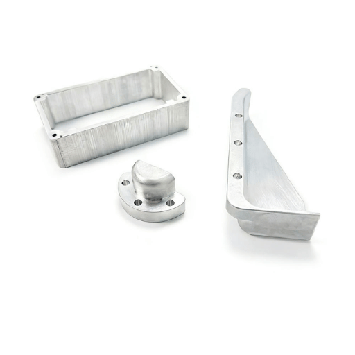
Aluminum 5052 is a corrosion resistant substitute for mild steel in architectural and marine applications. When higher strength is a design criteria, 6061-T6 is the standard. Engineers who need aluminum machining for tighter-tolerance features can combine sheet metal forming with secondary CNC operations.
Stainless steels 304 and 316L are corrosion resistant in many applications. For chemical applications or greater chloride resistance, using 316L offers advantages. Both 304 and 316L are suitable for forming, and sheet forming alloys are often combined with secondary CNC machining. Stainless steel parts requiring machined bores or threaded features pair well with a hybrid fabrication approach.
Carbon steel SPCC is the lowest cost sheet metal grade for closed environments. Copper parts serve thermal and electrical applications, while brass components offer a balance of machinability and corrosion resistance for decorative or RF-shielding uses.
When selecting sheet metals, search for the mill test certificates (MTC) from the supplier. These reports verify the actual tensile strength, ductility, and constituents in your batch, not just the specifications.

Poor sheet metal design is the single fastest method for driving up both cost and lead time. Following a proper DFM approach at the CAD stage eliminates rework, scrap, and the inability to meet press brake and laser cut tolerances.
Every bend must have a minimum inside radius to prevent corner cracks. The minimum tolerable radius depends on material – aluminum needs 2 times the material thickness (2T), mild steel needs 0.8T, stainless steel needs 1.5T-4T. Excessively small bend radii result in surface cracks in the outer bend radius if the grain direction is contacted.
Minimum flange length – the flat segment between the bend line and the sheet edge – has to be at least 2 times the material thickness PLUS the bend radius. Short flanges will slip out of the press brake die during forming and produce inconsistent angles.
📐 Engineering Note
For a 2 mm stainless steel 304 sheet with a 3 mm bend radius: minimum flange = 2 × 2 mm + 3 mm = 7 mm. Hole-to-bend clearance = 2 × 2 mm + 3 mm = 7 mm. Place all features at least this distance from any bend line to prevent deformation.
Holes, slots and cutouts located too close to a bend line will deform during the forming process. As before, 2 × the material thickness plus the bend radius is the safe minimum distance. Hole size should be at least equal to the material thickness (minimum 1T). CNC punch presses will make smaller holes but require custom tooling and special setup, adding significant cost.
ISO 2768 defines general tolerance classes for sheet metal parts. Most fabricators default to ISO 2768-mK, where “m” (medium) governs linear dimensions and “K” (medium) governs geometric tolerances like flatness and perpendicularity after bending.
| Nominal Length | Fine (f) | Medium (m) | Coarse (c) |
|---|---|---|---|
| 0.5 – 3 mm | ±0.05 mm | ±0.1 mm | ±0.2 mm |
| 3 – 6 mm | ±0.05 mm | ±0.1 mm | ±0.3 mm |
| 6 – 30 mm | ±0.1 mm | ±0.2 mm | ±0.5 mm |
| 30 – 120 mm | ±0.15 mm | ±0.3 mm | ±0.8 mm |
Another area where cost is hidden is in tolerancing of multi-bend components. Each bend adds about 0.25 mm in dimensional uncertainty. A part with four bends has an accumulated 1.0 mm total positional tolerance. Where tight features are necessary on custom parts, machining to tight tolerances after forming the sheet metal part costs less than imposing tighter tolerances on the entire piece of metal. For complex prototypes requiring fast iteration, rapid prototyping services can validate DFM assumptions before committing to production tooling.
Sheet metal fabrication cost depends on five factors. Whether you are ordering production parts or a single prototype, controlling these variables at the sheet metal design stage keeps pricing predictable.
| Cost Driver | Typical Range | Impact on Unit Price |
|---|---|---|
| Material | $2–15/kg (varies by grade) | 30–50% of part cost |
| Cutting | $80–150/hr (laser) | 5–15% per part |
| Bending | $60–120/hr (press brake) | 10–20% per part |
| Finishing | $0.50–5.00/part | 5–25% per part |
| Volume | Prototype $15–$200+/part, Production $5–$75/part | 2–10× cost difference |
Production volume dominates. The cost differential of prototyping versus production quantities far exceeds raw material price differences. Setup time on a single part runs between $50–$200, while at 1,000 units the cost is often only $5–$15 each. Switching from stainless steel 316L to aluminum 5052 can reduce material cost by 40–60% and cut weight by over 65%.
Design geometry also has a direct impact on tolerances and machine time. Each additional bend adds a press brake cycle, and requesting ISO 2768-f instead of ISO 2768-m may require secondary inspection or CNC milling passes, increasing cost 20–50%. Rush orders carry a 20–40% surcharge over standard lead times.
Minimize cost without lowering function by applying tolerances only to critical dimensions. Default to ISO 2768-m and specify tighter values only where mating surfaces or assembly fits require. This single change saves 15-30% in inspection and rework costs.
Ready to get a quote on your metal fabrication project? Le-creator’s custom sheet metal fabrication service provides 24-hour quote turnaround with DFM feedback included.

Design for Manufacturability. Ensuring that new or improved sheet metal components can be made cost effectively the first time by the sheet metal fab house. Avoiding rework saves time and money.
Sheet metal finishing protects against corrosion, enhances wear resistance, and finalizes the part’s look and feel. Choosing the ideal finish depends on the base metal, environment, and cost constraints.
| Finish | Thickness | Best For | Standard |
|---|---|---|---|
| Powder Coating | 60–120 μm | Steel, Aluminum (outdoor exposure) | ASTM D3451 |
| Anodizing (Type II) | 5–25 μm | Aluminum only | MIL-A-8625 |
| Zinc Plating | 5–25 μm | Carbon Steel (indoor/mild outdoor) | ASTM B633 |
| Passivation | Chemical (no build-up) | Stainless Steel | ASTM A967 |
| Brushing / Grinding | N/A (surface texture) | Stainless Steel, Aluminum (cosmetic) | — |
| Chromate Conversion | 0.25–1 μm | Aluminum (electrical conductivity) | MIL-DTL-5541 |
Powder coating is the most popular sheet metal finishing option for parts exposed to weather. Electrostatically applied and cured at 180–200°C, powder coating forms a 60–120 μm layer tougher than liquid paint. For aluminum sheet metal components, anodizing creates an oxide layer that is part of the base metal itself — it cannot peel or flake. Zinc plating on carbon steel provides sacrificial corrosion protection at low cost, though the 5–25 μm layer offers limited lifespan in harsh environments. Passivation strips free iron from stainless steel surfaces and restores the chromium oxide layer that guards against corrosion.
Most rework on sheet metal fabrication projects originate from five challenges at the design stage. Avoiding them can save money and lead time.

Production runs cost $5–$75 per part, depending on size and style; in prototype volume the cost is typically between $15 and $200+ each. The key factors that affect cost include material type (stainless steel takes 3-5 times as long to machine as carbon steel per kilogram), form (increased number of bends added a small amount of time to the machining), the class of tolerance, and surface finishing. Volume is of course the most significant.
Usually, a 10x increase in volume results in a 50-70% decrease in price per unit, etc. Request quotes from several different fabrication companies.
Yes, laser-cutting and CNC press brake bending don’t require any dedicated tooling at all, so sheet metal prototyping allows for prototype runs of 1–5 pieces. Turnaround time can be anywhere from 3 – 7 business days for simpler parts. This puts prototyping well ahead of stamping (and procurement time) as a one-piece prototype die can cost $5,000+ and may take multiple weeks to produce.
In many cases, fabricators will accept STEP, IGES or DXF files and can even offer same-week turnaround time for simple geometries.
Looking for precision sheet metal components with quick lead-times and design for manufacturing assistance?
This book references published ISO and ASTM specifications, industry data from Precedence Research and Grand View Research, as well as technical specifications acquired from manufacturers’ packaging and shipping capabilities. The DFM rules and tolerance stacking examples are representative of what is utilized in common precision sheet metal shops that supply automotive, aerospace and electronics needs. All cost ranges are derived from 2024-2025 market data; prices will change depending upon location, volume and availability of materials.