

Supportive, Professional, Client-Focused Service
From prototypes to full-scale production, we’ve got you covered.


Updated July 2026 · Reviewed by the Le Creator technical team.
CNC machining and fabrication are two distinct manufacturing processes for producing metal and plastic parts: CNC machining cuts a part from a solid block, and fabrication cuts, bends, and welds it from a flat sheet. Engineering and procurement teams routinely confuse the two because the names overlap in casual use. Failing to choose the right process — or failing to recognize that a single assembly may require both — is a common mistake when ordering a part for the first time. This guide distinguishes between these processes, offers specific tolerance and cost figures, and covers the one aspect that most buyer guides overlook: what to do when an assembly requires a combination of machined and fabricated components.
| CNC machining tolerance | ISO 2768-m general (±0.1 mm mid-size); critical features to ±0.005 mm |
| Sheet metal fabrication tolerance | ±0.005 in (±0.13 mm) laser-cut edges; ±0.010 in typical formed features |
| Typical CNC lead time | 5-10 business days standard tolerance |
| Typical fabrication lead time | 3-5 days prototype, 5-10 days production |
| When to combine both | Assembly needs a precision-machined feature (bore, thread, mounting face) mounted in or on a large formed/welded structure |
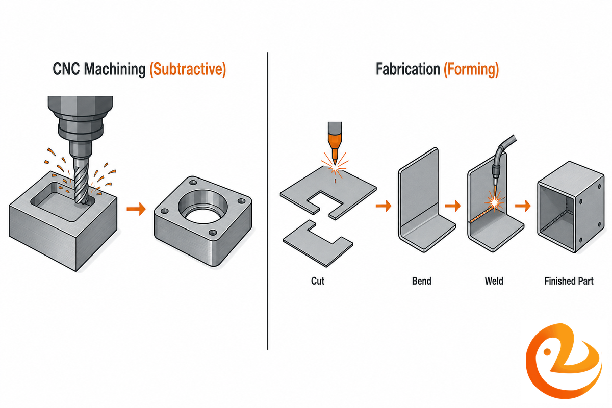
CNC machining (computer numerical control) is a subtractive manufacturing process: the machine, which can be a milling center, lathe, CNC router, or wire EDM, reads G-code generated from the CAD model to control a tool along a programmed toolpath and cuts a finished part from a solid piece of material to a specified engineering tolerance.
Fabrication, on the other hand, is a forming process, in which a flat sheet of material such as sheet metal is cut, bent, and welded to create an assembly. While both processes create functional parts, they differ significantly in their raw materials (solid block versus flat sheet) and approaches (removing material versus cutting and joining).
This fundamental difference accounts for most of the practical differences between the two processes. Machining is the natural choice for parts that require precise features such as threaded bores, close-tolerance bearing seats, or sharp internal geometric details that can’t be achieved through fabrication. Parts that primarily consist of thin-walled structures such as boxes, panels, and brackets are generally more cost-effective to fabricate, as machining them from a solid block would result in the removal and waste of a significant amount of material to achieve the final form.
| Attribute | CNC Machining | Sheet Metal Fabrication |
|---|---|---|
| Starting material | Solid billet, bar, or block | Flat sheet or plate stock |
| Core operations | Milling, turning, drilling, wire EDM | Laser/plasma cutting, press-brake bending, welding |
| Best part shape | Solid 3D features, bores, threads, pockets | Thin-wall boxes, brackets, panels, enclosures |
| Limitations | Expensive for large, mostly-hollow parts (wastes stock) | Cannot hold tight bores/threads or complex blind pockets |
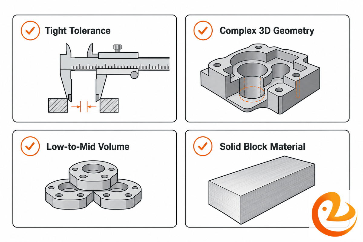
On tolerances specifically, machining offers a clear advantage for parts that demand tight dimensional accuracy, unique three-dimensional features that can’t be formed from a flat sheet, or small production volumes where the tooling cost associated with fabrication wouldn’t be justified by the order size.
Good CNC machining design starts with the same four factors procurement professionals actually use in their daily work: process, material, tolerance, and geometry — research on design for nonassembly generalizes these into a repeatable framework rather than a case-by-case judgment call, and you don’t need to use CNC for every feature just because the rest of the part is machined.
Check your part against these 4 machining criteria:
| Criterion | Threshold | Why it matters |
|---|---|---|
| Tolerance | Tighter than ±0.010 in on any feature | Fabrication’s press-brake and weld tolerances cannot reliably hold this |
| Geometry | Threaded hole, bore, or blind pocket | Cannot be cut or formed from flat sheet |
| Volume | Prototype to a few hundred units | No tooling cost, so per-part price stays reasonable at low volume; also the default route for a first-article rapid prototype before committing to production tooling |
| Material | Solid block/bar stock alloy or engineering plastic | Fabrication only works from sheet-form stock |
Specifically, Xometry’s published specification for precision machining states that the general tolerance for metal is ±0.005 inches (±0.127 mm), which corresponds directly to our own standard-tier milling tolerance. Having two separate machining shops state the same number is more conclusive than just one. A key aspect for enabling either shop to quote these tolerances is submitting a 3D CAD model (such as a STEP, IGES, or native SolidWorks file) rather than a 2D PDF.
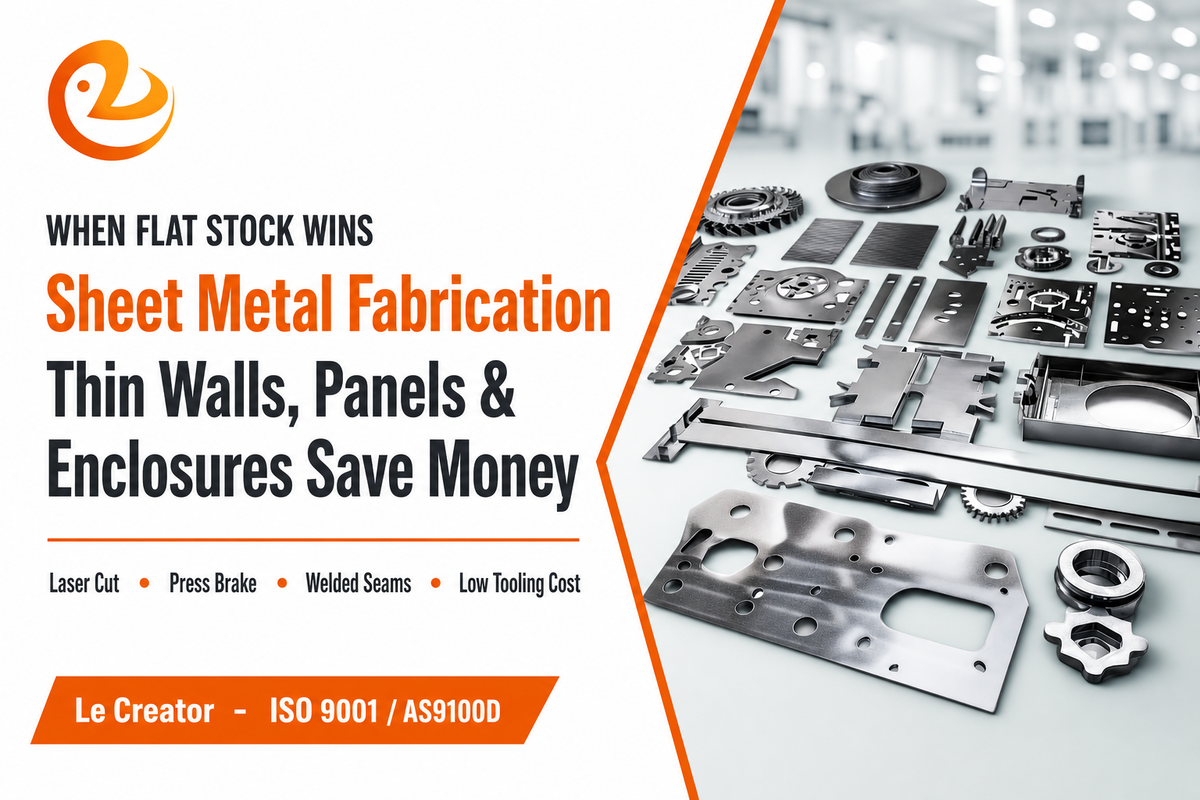
If your part is a thin-wall enclosure, bracket or panel made of flat stock, you’ll very likely save money choosing sheet metal fabrication over machining, because the initial material you start with is already close to the final form and needs less machine time to reach it.
A classic example: MJM Manufacturing reports it worked with a Fortune 500 OEM to slash tooling costs by over 95% by re-designing a part for precise sheet metal fabrication, instead of machining it from solid stock. While that’s a particularly dramatic figure, and applies to a part that was heavily over-machined to begin with, it highlights the level of wasted material a poor choice of process can cause.
Most of the action in this work is a laser cutting operation followed by a CNC press-brake bend. In fact, it’s estimated that on parts up to 1 in thick a fiber laser holds roughly ±0.005 in on the cut edge, and an up-to-date press brake can replicate a bend line in a multi-bend part with a 6-axis back gauge to the degree that no hand-fitting is necessary. The bent and welded parts form the skeleton.
The standard weld for the aluminum, stainless, or carbon steel parts here is either AWS-certified MIG or TIG welding, which provides a structural, not just visual, joint.
| Choose CNC Machining When | Choose Fabrication When |
|---|---|
| Part needs a threaded bore or bearing seat | Part is a flat, folded, or welded enclosure |
| Tolerance tighter than ±0.010 in anywhere | Sheet-metal tolerance (±0.010-0.005 in) is enough everywhere |
| Small-to-mid part cut from solid stock | Large, mostly-hollow structure or panel |
Neither process is cheaper and/or more precise across the board. A YouTube explainer titled “When CNC Machining Beats Sheet Metal Fabrication (5 Situations)” makes the case for the reverse as directly, and one fabricator plainly says the use of laser cutting “may not always be the most cost-effective option for thicker materials.” Here it comes down to geometry rather than a universal “best” choice.
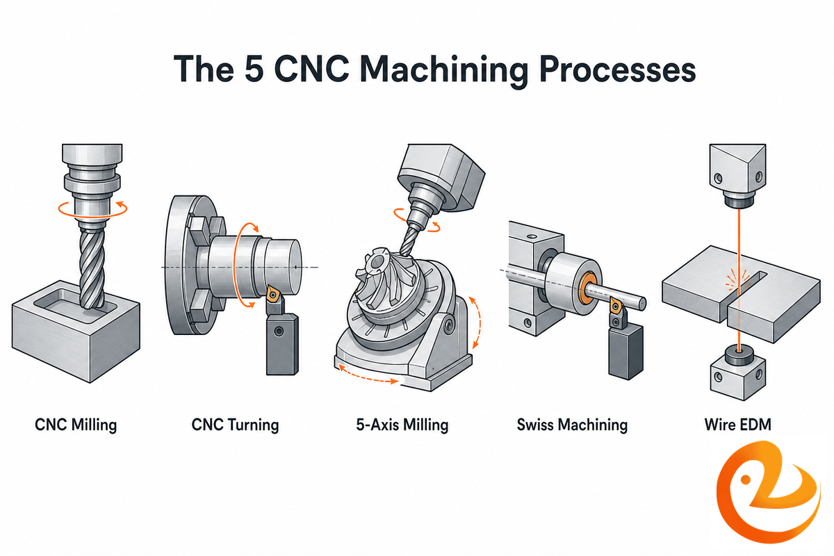
“CNC machining” covers a range of CNC machining processes — five distinct types of CNC machine and sub-process built around the same underlying CNC system and CNC equipment. Selecting the right one for the part geometry is where most novice buyers throw away a lot of time and money, and the correct process choice for part one will make a great deal more difference than you may first assume.
Modern CNC machinery, from 3-axis mills to 5-axis CNC machining centers, commonly runs spindle speeds up to 12,000 RPM, holds positioning repeatability within 0.005 mm, and travels envelopes up to 500 mm on a mid-size machine — most precision work is also run in shop floors held near 20°C to keep thermal drift out of tight-tolerance features, which is part of why a correctly matched process can cut cycle time substantially. A custom machining setup used for a one-off prototype can also run production parts and quick-turn parts once the machine is programmed successfully.
| Process | Best For | Typical Tolerance |
|---|---|---|
| CNC Milling | Pockets, holes, flat faces on prismatic parts | ±0.127 mm standard, ±0.01 mm ultra-precision |
| CNC Turning | Round parts — shafts, pins, bushings | ±0.001 in standard |
| 5-Axis Milling | Complex contours, undercuts, one-setup parts | ±0.025-0.05 mm |
| Swiss Machining | Small, high-volume precision parts | ±0.0001-0.0002 in |
| Wire EDM | Hardened tool steel, sharp internal corners | ±0.0001 in |
It deserves a special mention for wire EDM, though: Of all the processes on this list, it’s the only one that actually uses electrical erosion to remove material instead of a mechanical cutting tool. That makes it able to cut hardened tool steel up to 62 HRC, which would wreck a regular cutting tool – handy for making a locating pin or die feature in a manufactured assembly that’s hardened after manufacturing. Bore-heavy parts — hydraulic cylinder tubes, sleeves, bushings — often need one more step after milling or turning: precision honing.
That step is necessary to correct any roundness errors and to put a repeatable, crosshatched finish on the bore that no other cutting method can produce.
Is your part round and also milled flat? If yes, ask your supplier whether it runs mill-turn — combining CNC turning with live tooling in a single setup eliminates repositioning error between two separate machines.
At the process level, CNC milling is a subtractive operation that cuts solid plastic and metal blocks into final parts by removing material along a programmed toolpath using cutting tools and other machining tools mounted in an automatic tool changer, while CNC turning spins the workpiece against a fixed or live cutting edge to machine parts with cylindrical features — a mill’s capabilities to machine parts with flat and pocketed geometry, and a lathe’s capabilities to turn round profiles, complement each other rather than compete. Recognizing CNC milling and CNC turning as the two workhorse processes explains why most shops built their core CNC machining capabilities around those two machine types before adding 5-axis, Swiss, or wire EDM machinery for niche geometry. In practice, CNC machining is widely used across both prototypes and production parts because the same CNC precision and repeatability, and the same as-cut CNC machining surface finish of roughly 1.6 to 3.2 µm Ra, apply whether the job calls for one milled part or multiple parts across a production run — a bearing-adjacent bore can be specified down to about 0.4 µm Ra when a smoother finish is required.
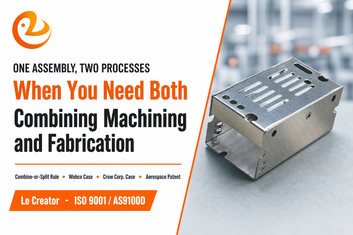
Many real assemblies aren’t purely machined or purely fabricated — a welded frame with machined mounting pads, or a fabricated enclosure with a precision-machined shaft passing through it, is a normal engineering outcome for a mixed-process assembly, not an edge case.
Real fabrication shops that already run both processes under one roof give the clearest evidence for this: at Webco Manufacturing (Olathe, Kansas), managers brought CNC turning in-house because “customers had sensitive, time-critical parts,” and the shop now runs laser cutting, press-brake bending, and machining concurrently on the same assemblies. At Crow Corp. (Tomball, Texas), roughly 40% of the machine shop’s work is fully machined, about 10% is tooling and fixturing, and the remaining 50% is machined components that go into larger weldments and fabricated assemblies, per company president Keith Jennings.
“As we’re doing laser and brake work, we can be machining parts that will be welded.”
— Mike Johnson, Vice President, Webco Manufacturing
The Combine-or-Split Rule: if any single feature on the part needs a tolerance tighter than fabrication can hold (a bore, a threaded hole, a precision mounting face), split that feature into a separate machined component and fabricate the rest of the structure around it. If every feature on the part can live within fabrication’s tolerance band, keep it as a single fabricated part — don’t machine the whole thing “to be safe,” because that trades a fabrication-level cost for a machining-level one without a functional reason.
A patent filed for an aircraft fuselage assembly fixture illustrates the same logic at industrial scale: the design integrates sheet-metal joints with machined and assembled fixture components into a single manufacturing system, rather than treating the sheet-metal and machined portions as separate projects. This same pattern holds from a single bracket up to an aircraft structure — machine the features that need precision, fabricate the structure around them.
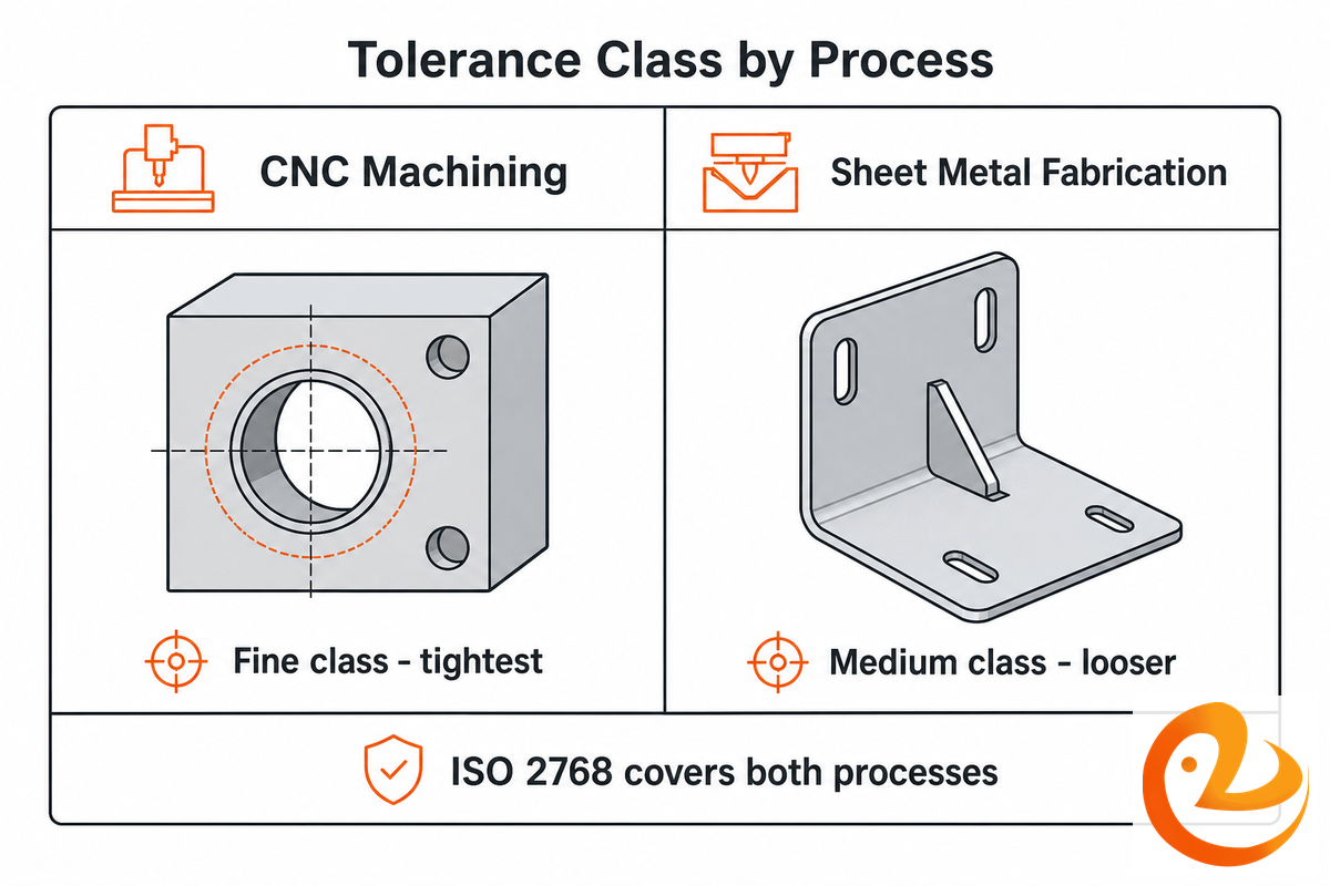
ISO 2768-1 is the standard most shops default to for general tolerances, and it applies to dimensions on parts produced by metal removal (machining) as well as parts formed from sheet metal — it is not a machining-only standard the way it is sometimes shorthanded.
Where it differs by process is the tolerance class typically applied: precision machined features are commonly called out at the Fine class (roughly ±0.05 mm at mid-size), while sheet-metal parts and large fabricated structures are more commonly specified at the Medium class, because tight fits are rarely critical across an entire formed or welded structure. For geometric tolerancing (position, flatness, perpendicularity) rather than simple linear dimensions, the relevant standard has moved on from the older ISO 2768-2, which has been withdrawn in favor of ISO 22081:2021 — worth checking which edition your supplier is actually quoting against.
ASME equivalents are frequently specified by US suppliers over ISO equivalents; ASME Y14.5 is broadly equivalent to ISO 2768 on general/geometric tolerancing, and ASME B4.1 is the US equivalent of ISO 286 on cylindrical fits. Either set is fine, although you should clarify which standard applies on your drawing before requesting a quote. Be aware that mixing standards on a single drawing can create review delays when ordering.
| Attribute | CNC Machining | Sheet Metal Fabrication |
|---|---|---|
| General tolerance | ±0.127 mm (Fine class) | ±0.13-0.25 mm (Medium class) |
| Best achievable | ±0.005-0.01 mm | ±0.005 in on laser-cut edges |
| Materials | 40-50+ metals/plastics (bar, block, plate) | Steel, stainless, aluminum, copper (sheet, plate) |
| As-machined surface finish | Ra 1.6-3.2 µm typical | Depends on cut/bend process, often needs secondary finishing |
| Limitations / not suitable for | Large, mostly-hollow parts (excess stock waste) | Tight bores, threads, or blind-pocket features |
The selection of materials will influence more than just cost, and the choice applies to metal and plastic parts on either side of the machine’s cutting tool. Both the machining and fabrication processes are well-supported by aluminum (aluminium) and stainless steel, which provide a balance of strength with formability and corrosion resistance while minimizing the need for specialized tooling; stainless owes its corrosion resistance to its chromium content, and many alloy steels owe their toughness under load and wear resistance to their manganese content — both are strength of materials fundamentals worth confirming on the mill certificate. Machine shops commonly also offer computer-aided design (CAD) programming and machining of engineering thermoplastics, which are difficult to fabricate from sheet: polyether ether ketone (PEEK) and polyetherimide (Ultem) withstand sustained high temperatures and have good electrical resistance and electrical resistivity for insulator parts, POM (acetal) and nylon cut cleanly with low friction for parts located adjacent to bearings, and common plastics like polycarbonate, acrylonitrile butadiene styrene (ABS), polyvinyl chloride (PVC), polytetrafluoroethylene (PTFE), and high-density polyethylene (HDPE) cover lower-stress parts and prototyping. After machining or fabrication, anodizing is the most common metal finish that’s called out; this process enhances corrosion resistance and wear resistance without changing part dimensions, and the properties worth checking on a material certification for any part subject to cyclic load are ultimate tensile strength, ductility, and fatigue limit — aerospace parts under ITAR export control are the clearest example of where that certification actually gets checked.
For pricing, there’s no single universally cited data source; there are several engineering forum discussions where participants suggest that machined parts cost from five to several hundred times the price of their raw materials. For most parts, that works out to something like $5-$500 depending on machining time, a range that’s too broad to be used reliably for estimation, though it’s a good mental check. Features, however, are a far better guide than the process label; additional bends and holes and extra setups on a fabrication add handling, while additional setups and deep pockets and tighter tolerances add machine time, to make part pricing correlate much more strongly with features shown on the drawing than the name of the process on the quote.
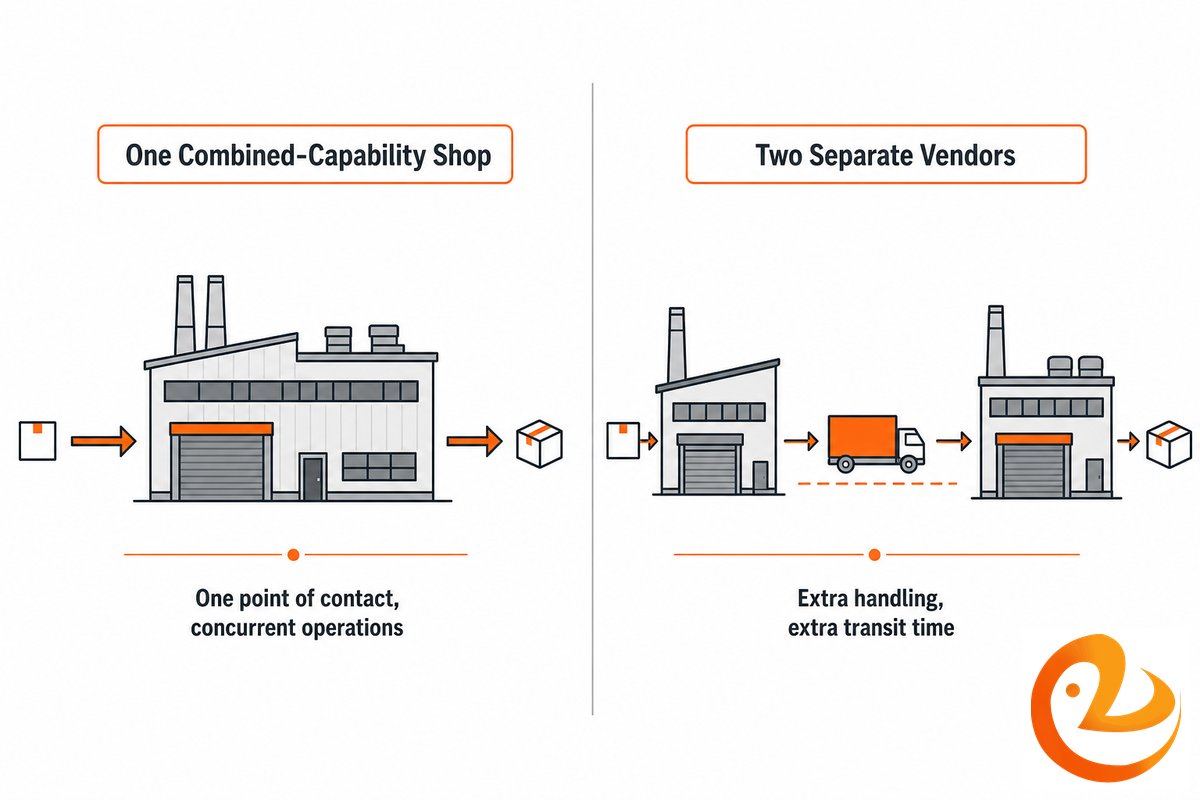
For a part that needs to be either fabricated or machined, buyers may seek a supplier capable of doing both or use two specialized vendors for a handoff. Based on real-world evidence, the former is often preferable, at least for a combined weldment that requires machining and fabricating; Webco Manufacturing acquired in-house machining capabilities, partly to allow them to “run [machining, laser and brake] operations concurrently” for a single weldment and to avoid the extra handling involved in shipping a part back and forth to another company. A graduate research thesis on integrating additive and CNC sheet-metal fabrication under one production workflow reaches a similar conclusion at a more advanced level: process integration under one roof reduces handoff losses in mixed-process manufacturing.
5-Factor Process-Fit Selector Framework — match your part to a sourcing path:
| Factor | Priority Tier | One Supplier (both processes) | Two Vendors (split by process) |
|---|---|---|---|
| Coordination overhead | High | Low — one point of contact, one schedule | Higher — shipping/hand-off between two shops |
| Lead time | High | Shorter — concurrent operations on one floor | Longer — adds transit + queue time between vendors |
| Tolerance-matching risk | High | Lower — same QC system checks both halves | Higher — two separate inspection standards to reconcile |
| Specialist depth per process | Medium | Can be shallower if machining is a smaller side capability | Each vendor is a specialist in one process only |
| Engineering change turnaround | Medium | Faster — one drawing revision, one shop to notify, often under 24 hours | Slower — both vendors must independently re-quote the change |
| Tooling and fixture reuse | Medium | Shared fixturing across runs is easier to schedule | Each vendor maintains separate fixture inventory |
| Freight and handling cost | Low | Lower — no inter-shop shipment of in-process parts | Adds a freight leg per batch between the two shops |
| Best for | — | Recurring assemblies needing both processes together | One-off parts, or when one process needs deep specialist capability (aerospace-grade 5-axis, for example) |
Just one important caveat to be said upfront: this isn’t a general argument that fewer suppliers always reduce risk. Supply chain literature always makes supplier diversity a strategy for overall supply base resilience, and that logic carries over to your problem of “who else could do this if my primary shop is down.” The consolidation benefit I’ve cited here is confined to machining-and-fabrication for one part or assembly, where switching from vendor A to vendor B for the second step only adds complexity and cost – it has no risk-mitigating benefits. You don’t want to source your whole supply base from one supplier. If you don’t believe this, get a quote for your same drawing from a combined-capability CNC machining manufacturer, and then get one from a standalone machining factory and a separate fabrication shop, and compare how much money and lead time you save by consolidating. It’s worth noting that an instant quote or online quote tool from a CNC machining service online is genuinely useful for a simple, single-process part — but an order custom request that spans both machining and fabrication on one assembly is exactly the case where a live engineering conversation, not an automated online cnc machining service calculator, catches the tolerance-matching issues this guide covers. To receive a quote that actually accounts for both processes, send the full assembly drawing, not just the machined or fabricated half.
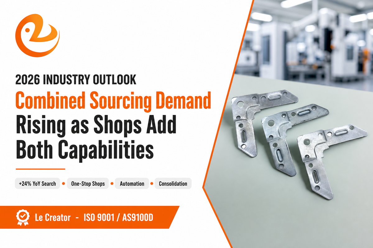
Combined machining and fabrication is an area with rising buyer search and procurement interest, as DataForSEO shows through search volume data for the phrase “cnc machining and fabrication.” That has gone up 24% year-over-year and about 58% versus its level two to three years ago. That rise isn’t an anomaly; trade press accounts suggest production shops are adding capacity and processes in machining and fabrication precisely to become “one-stop shops” and spare their customers from the task of dealing with multiple vendors.
I need to be precise, however. What’s growing is buyer interest in and demand for the consolidated machining and fabrication services, not the U.S. manufacturing workforce. Bureau of Labor Statistics figures project employment for metal and plastic machine workers to drop 7% between 2024 and 2034; employment of machinists, and tool-and-die makers is projected to decline by around 2%; sheet metal workers are expected to grow by about 2% in that same period. Those two trends aren’t necessarily contradictory. Advances in automation, unattended operation, and lights-out CNC are reducing the labor intensity of any amount of machining or fabrication capacity. Meanwhile, buyer demand to consolidate procurement by single-sourcing machined and fabricated components continues to rise. In practice, what’s happening is that more CNC shops now possess both the machining and fabrication capabilities to profitably do business on that kind of part than a few years ago, which makes consolidating a machined-and-fabricated part onto a single supplier much more feasible.
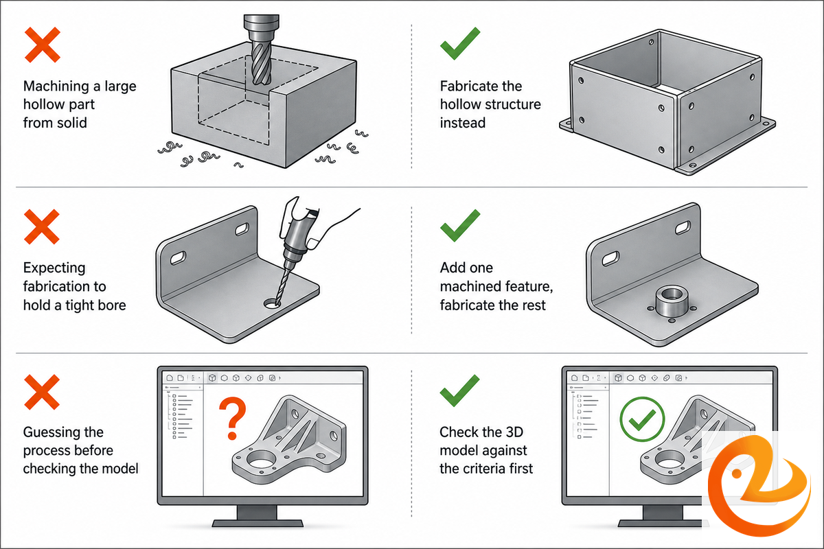
Two real buyer threads on a machinist forum illustrate the same underlying problem. One buyer asked how to source a simple bracket; another asked how to approach a cable tray riser. Both threads show engineers defaulting to whichever process they know best, rather than checking the part against the criteria above. In both cases, the CAD model itself would have answered the question in minutes — most process-selection mistakes are visible on the drawing before a single quote goes out.
The mismatch can go the other way. Over-machining a part that really just needs a few close-tolerance features throws away raw material and machine time on features that don’t need it – the extreme case of this is illustrated by the MJM case study. Under-specifying a fabricated part that really needs a machined hole or boss results in a sub-assembly that doesn’t assemble and must be reworked with a last-minute emergency machining order – which will inevitably be more expensive and slower than doing it right from the start. Custom parts cut from solid stock, a fabricated part welded from sheet metal – however you correct the mismatch, doing it on the drawing is the most effective method for keeping a prototype order from escalating into a production-line problem.
Taken together, this guide is meant to work as a practical reference for anyone trying to learn what CNC machining actually covers before requesting a quote: a manufacturing process that uses a programmed toolpath to cut parts requiring tight tolerances, alongside a fabrication process that uses sheet stock for larger, thinner structures. A wide variety of CNC machining and fabrication requirements — from a single cnc machined prototype to a production run of cnc-machined parts — come down to matching the process to the feature, not to a generic sense of which service sounds more advanced. This is also a good point to flag what this guide does not replace: it’s a process-selection reference, not a substitute for CNC machining design tips specific to your part, and it does not cover 3D printing and CNC machining as an alternative pairing (see our separate CNC Machining vs 3D Printing comparison for that decision).
Le Creator Technology Co., Ltd. is a combined CNC machining and fabrication manufacturing service: our fabrication experts and machinists run CNC milling, turning, Swiss machining, and wire EDM alongside laser cutting, press-brake bending, and AWS-certified welding under one roof — the sourcing comparison in this guide reflects how we actually route mixed-process assemblies through our own shop floor, not a hypothetical. Our CNC services cover both prototype and production volume work, certified to ISO 9001:2015, IATF 16949, AS9100D, and ISO 13485.
These CNC machining FAQs answer the questions that come up most often once buyers have read the process-selection guidance above.