

Supportive, Professional, Client-Focused Service
From prototypes to full-scale production, we’ve got you covered.


Wire cut manufacturing guide for engineers: learn Wire EDM limits, tolerances, kerf, skim cuts, material fit, and when to use it beside CNC machining.
Manufacturing Guide
Wire cut is a common shop-floor term for Wire EDM, a non-contact electrical discharge machining method used when hard conductive parts need controlled profiles, tight inside corners, careful kerf planning, or low mechanical cutting force.
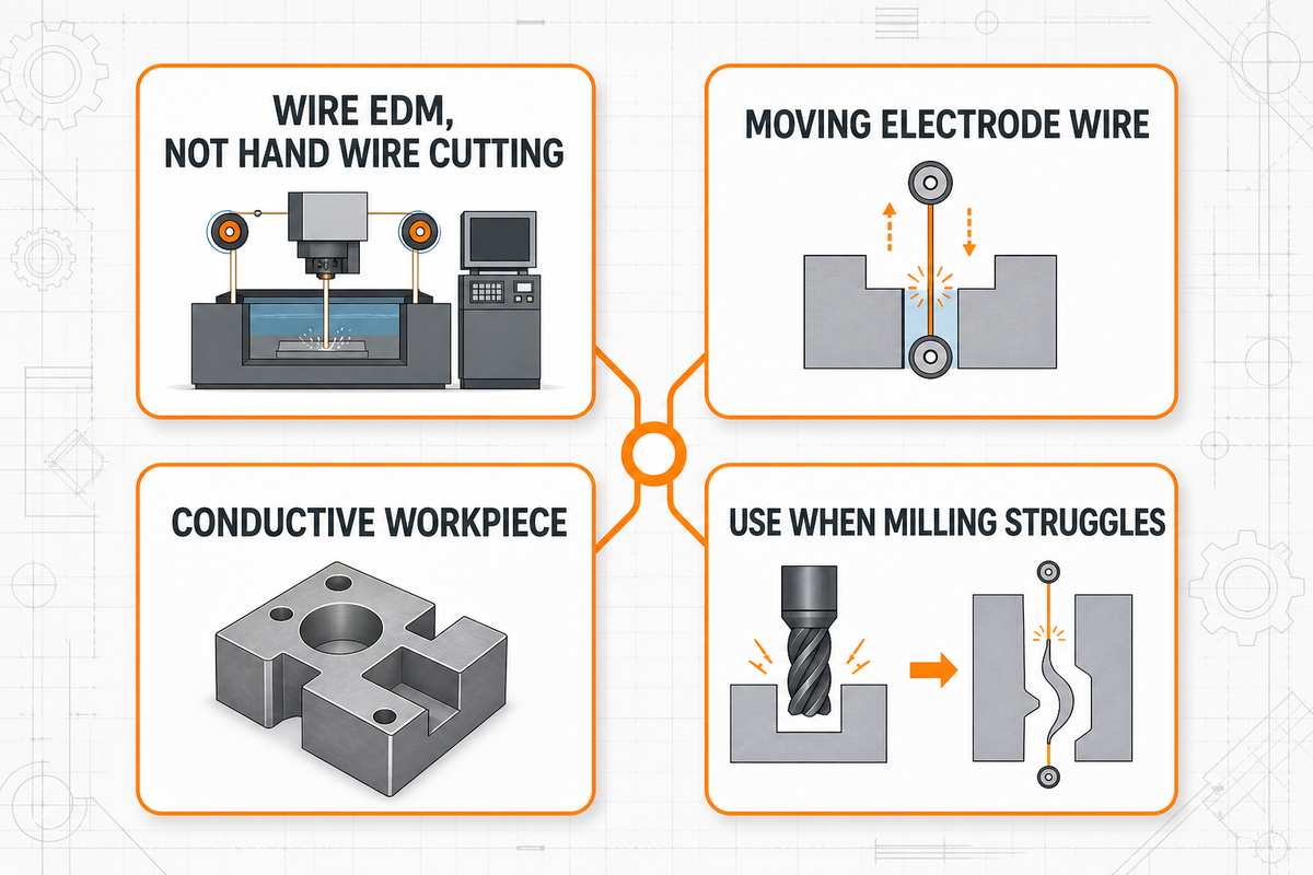
In manufacturing, wire cut usually means Wire EDM rather than hand-tool cutting, wire stripping, software trimming, or haircut language. A thin moving electrode wire, dielectric fluid, controlled spark energy, and CNC path control remove material from an electrically conductive workpiece. Engineers normally consider it when milling, laser cutting, waterjet cutting, or sinker EDM would struggle with hardness, thin walls, fine slots, sharp internal radii, or heat-treated material.
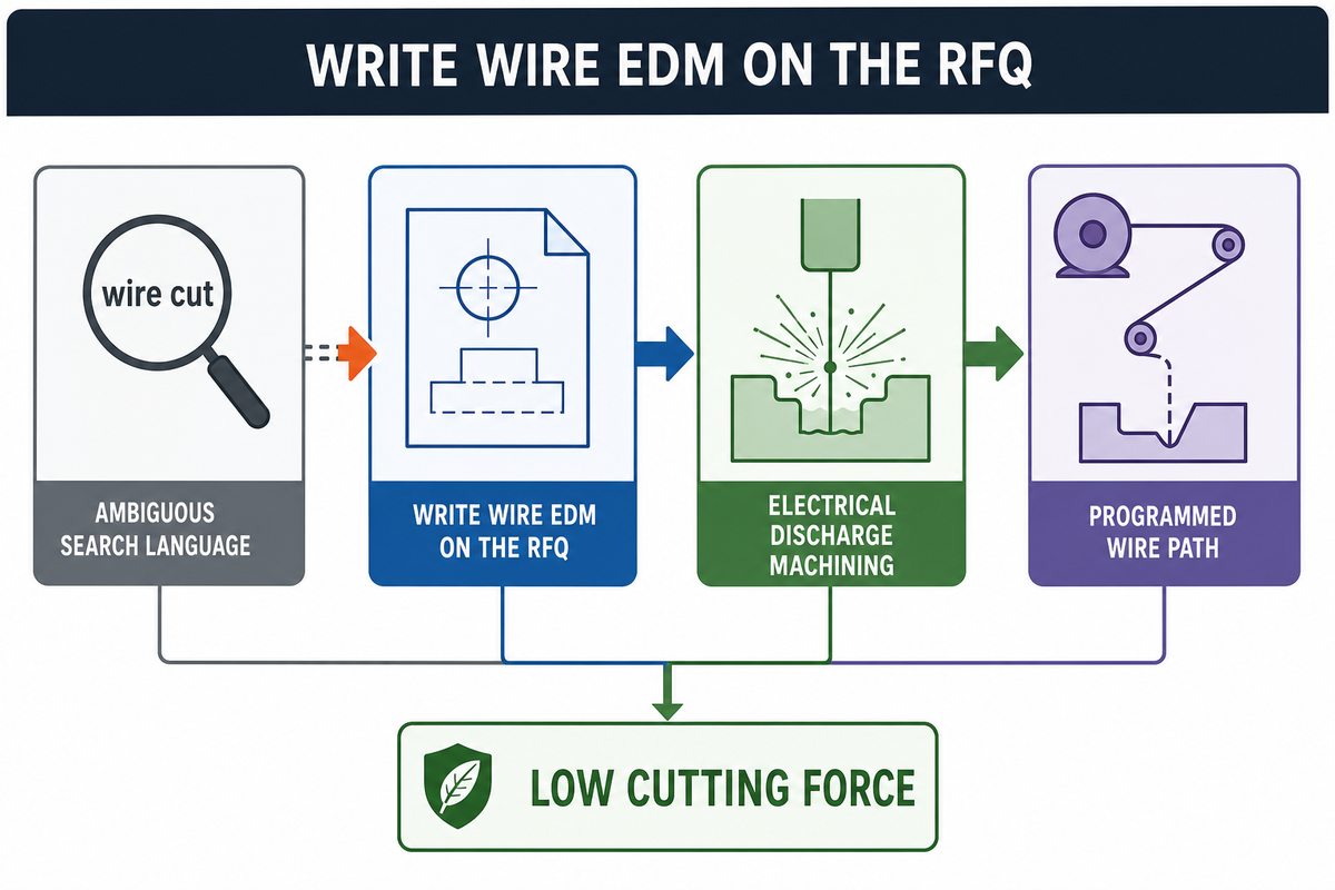
Wire cut, in an engineering RFQ or machining review, normally points to Wire EDM. The phrase is ambiguous in search results, so a drawing note should say “Wire EDM” when that is the intended process. That one word change separates manufacturing intent from manual wire cutters, software commands, bricks, and other unrelated meanings.
Wire EDM belongs to electrical discharge machining. Instead of forcing a rotating tool through material, the machine feeds a small electrically charged wire along a programmed path. Spark discharges erode a narrow slot through the workpiece while deionized water helps control debris and temperature. Because the method is non-contact, cutting force is low compared with milling or sawing.
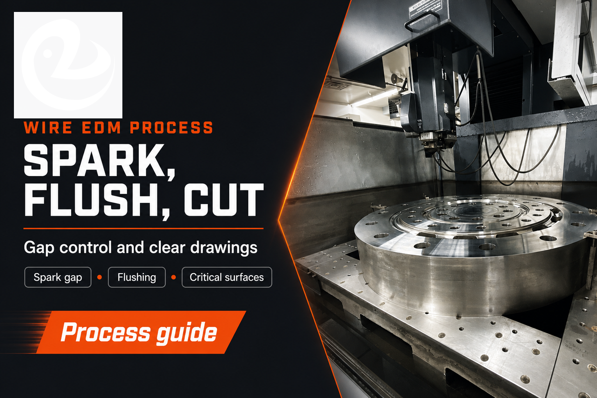
The wire is not a saw blade. It acts as a moving electrode. A controlled gap is kept between the wire and the workpiece, and electrical discharges remove small amounts of material along the programmed path. The wire is continuously fed, so the cutting edge is renewed as the job runs. An EDM machine controls the wire path, spark gap, feed, and liquid dielectric conditions; the drawing still needs to tell the shop which surfaces matter.
Computer numerical control guides the path, but accuracy and precision still depend on setup judgment. A stable program cannot fix an unclear datum scheme, a missing start-hole callout, or a finish note that treats every edge as equally important.
Deionized water matters because debris in the cut slot affects spark stability, surface quality, and speed. Poor flushing can lead to unstable cutting, wire breaks, taper variation, rougher surfaces, or more finishing time. For thick parts, stacked parts, tiny slots, and enclosed contours, the setup plan often matters as much as the machine capability.
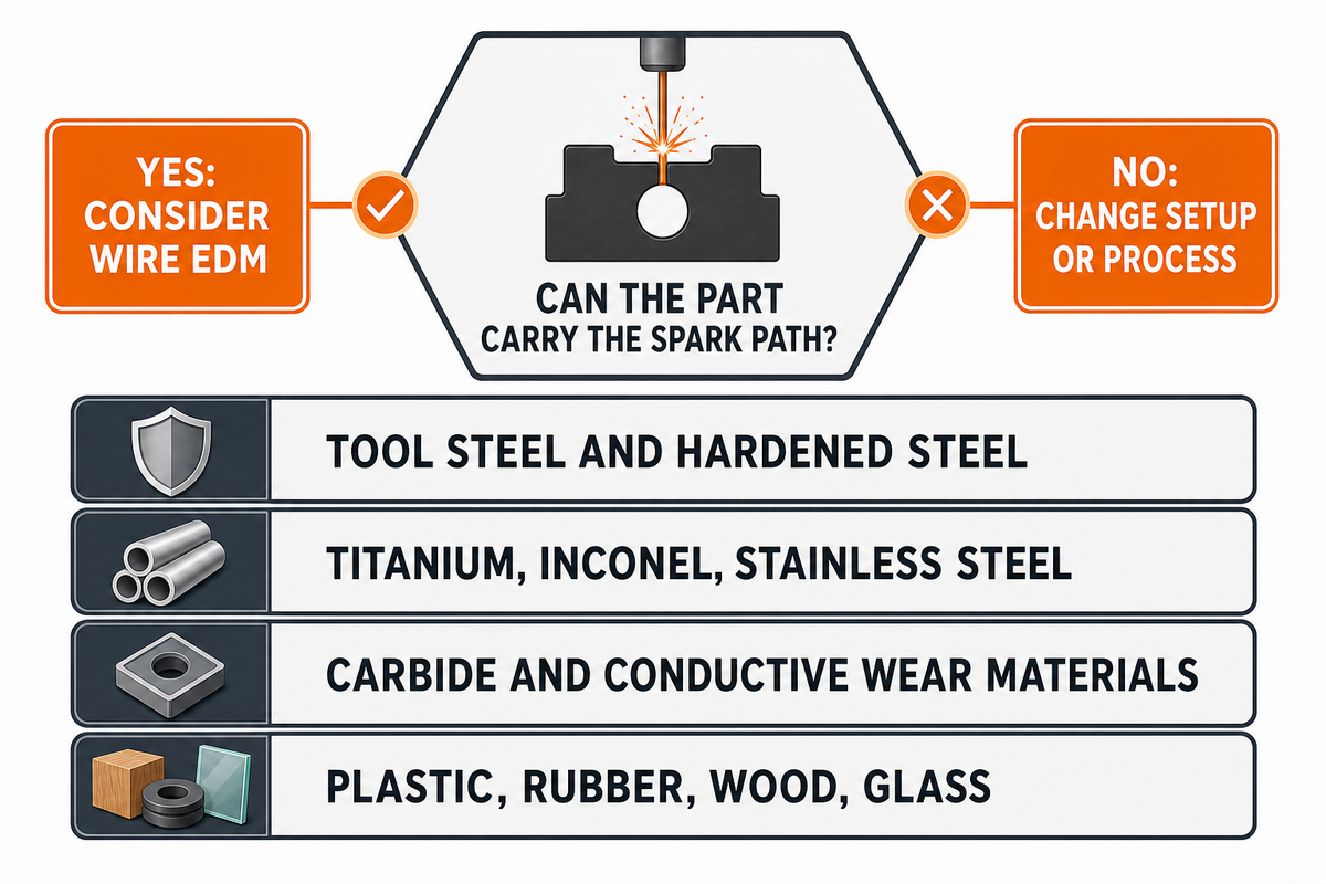
This is the first decision gate: can the part carry the EDM spark path? If yes, wire-cut EDM can be considered. If no, the method is usually out unless the design uses a special conductive aid or a different process is selected.
| Material family | Wire-cut fit | Engineering note |
|---|---|---|
| Tool steel and hardened steel | Strong | Often considered after thermal processing to avoid tool wear and distortion from heavy cutting force. |
| Titanium, Inconel, stainless steel | Strong with review | Check thickness, finish, and surface integrity, especially for aerospace or high-duty parts. |
| Carbide and conductive wear materials | Often suitable | Plan support, flushing, and finish cuts carefully because chipping or edge quality can drive acceptance. |
| Plastic, rubber, wood, glass | Usually unsuitable | Look at CNC routing, laser, waterjet, molding, or additive options instead. |
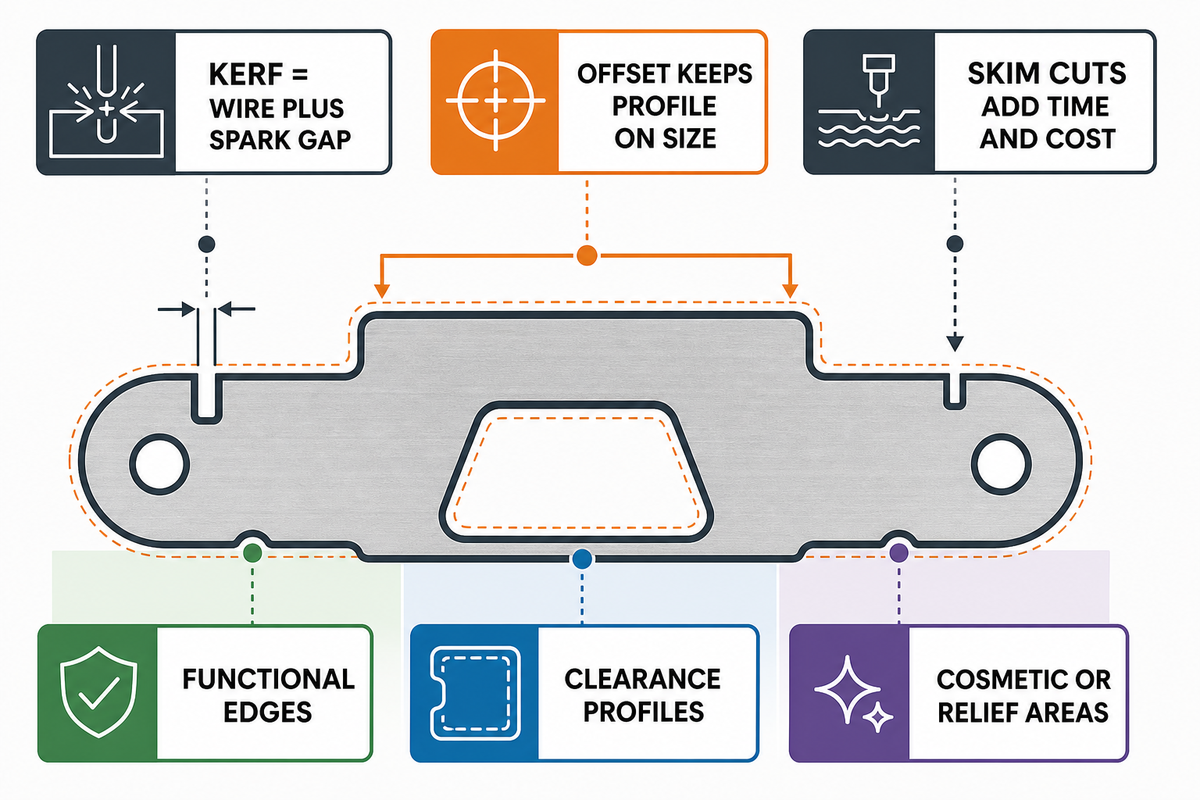
The wrong way to specify this process is to ask for the tightest tolerance everywhere. Better drawings identify which features truly control function and which ones can remain general profile cuts. Wire diameter, spark gap, offset, material thickness, flushing, corner strategy, and inspection method all affect the final dimension.
Kerf is the slot removed by the wire and spark gap. Wire offset is the programmed compensation that keeps the final profile on size. Skim cuts are light finishing passes after the rough cut. They can improve size control and surface quality, but they also add time and cost. A part with two functional sealing edges may need skim cuts only on those edges, not around every clearance pocket.
Before quoting, split the print into three zones:
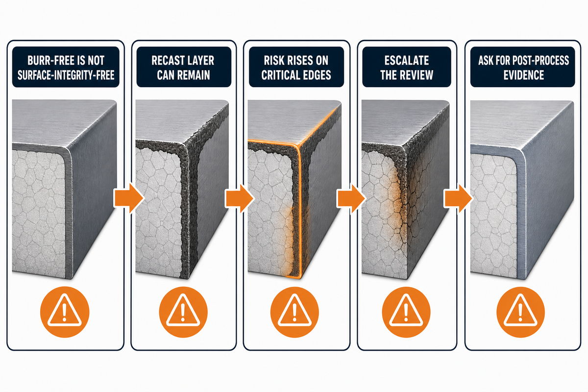
Wire-cut parts are often praised as burr-free, but burr-free is not the same as surface-integrity-free. EDM energy can leave a recast layer and may change surface roughness or microstructural condition. Research on EDM surface integrity and recast layer behavior shows that discharge energy, pulse timing, material condition, and flushing can affect the final surface.
That does not mean every wire-cut edge is a problem. Many production parts run successfully with normal EDM finish. Risk rises when the cut surface sees fatigue loading, sealing, sliding wear, high stress concentration, or documented aerospace requirements. In those cases, the drawing or purchase note should call for the required finish, post-process step, and inspection evidence.
Escalate the review when the cut edge is a fatigue edge, seal land, bearing face, sliding interface, regulated contact surface, pressure boundary, or part of a high-value assembly. Ask whether a skim pass, polishing, electropolishing, stress relief, or cross-section inspection is needed before release.
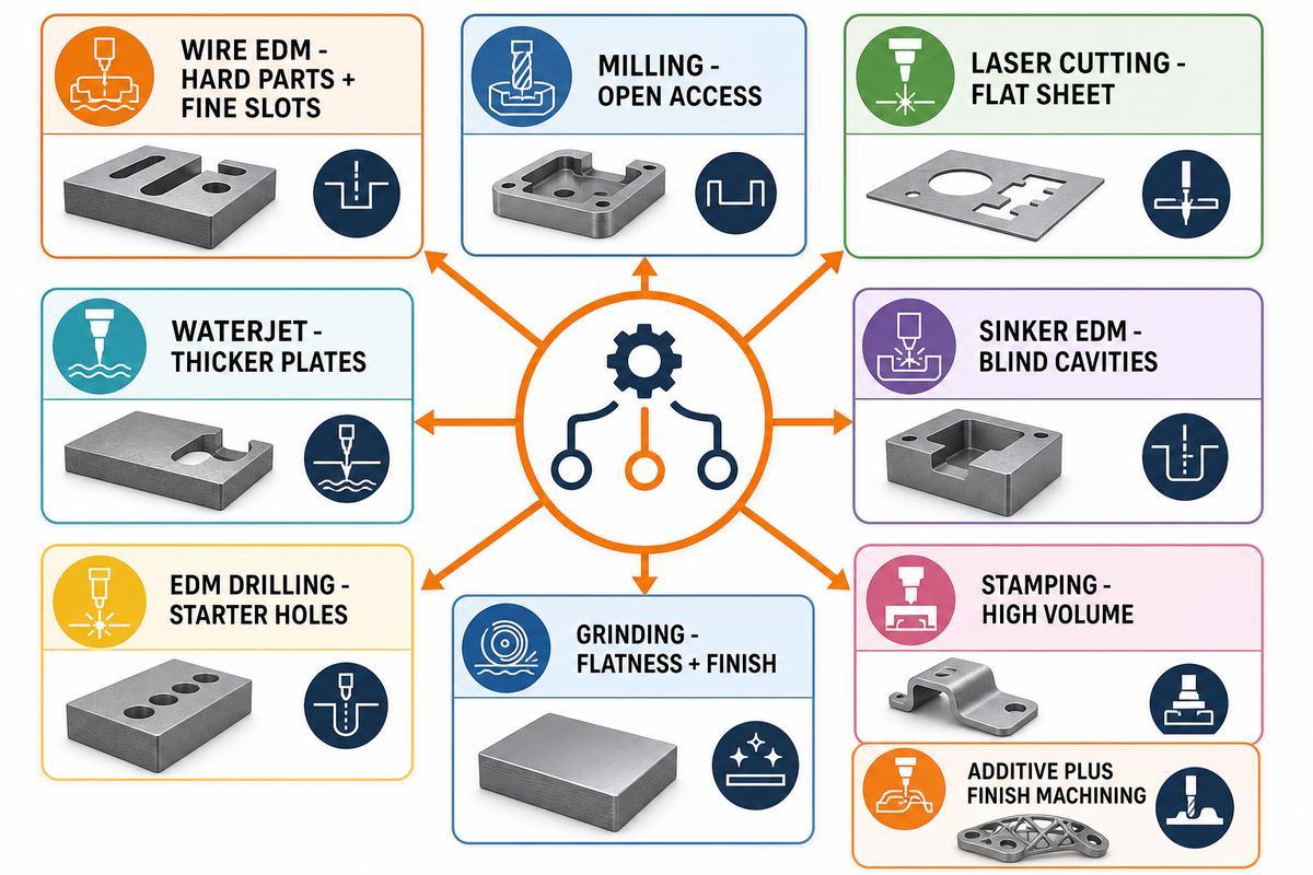
Wire EDM is powerful, but it is not the default answer for every precise part. Process choice depends on geometry, material state, edge condition, tolerance, finish, thickness, and quantity. A fast milled pocket may beat EDM cutting when the material is soft and tool access is easy. EDM wins attention when cutting force, tool wear, sharp internal corners, or hardened stock change the economics. Conventional EDM still has a role for blind cavities, while a traveling wire is better for through-cut profiles.
| Type | Choose it when | Watch out for |
|---|---|---|
| Wire EDM | Conductive hard parts, fine slots, thin walls, closed profiles, sharp internal corners. | Slower cycle time, start-hole needs, recast layer review, wire access limits. |
| Milling | Open access, good tool reach, softer stock, volume where speed matters. | Tool deflection, corner radius limits, tool wear in hard material. |
| Laser cutting | Flat sheet, high speed, looser edge or heat-affected requirements. | Heat effect, taper, edge finish, reflective material constraints. |
| Waterjet | Thicker plates, mixed materials, low heat input, rough profiling. | Taper, abrasive edge quality, accuracy limits on fine features. |
| Sinker EDM | Blind cavities, ribs, mold details, forms a traveling wire cannot reach. | Electrode design, electrode wear, more setup planning. |
| EDM drilling | Starter holes for closed profiles, tiny cooling holes, or hard material pilot holes. | Hole location, diameter, breakthrough burr, and downstream threading access. |
| Grinding | Flatness, parallelism, and finish after thermal processing drive acceptance. | Corner access, burn risk, fixture time, and limited pocket geometry. |
| Stamping or fine blanking | High volume justifies tooling and edge condition can be proven. | Tooling cost, design freeze, burr direction, and change control. |
| Additive plus finish machining | Complex shapes are difficult to cut from billet and surfaces can be finished later. | Material properties, datum plan, support removal, and finish allowance. |
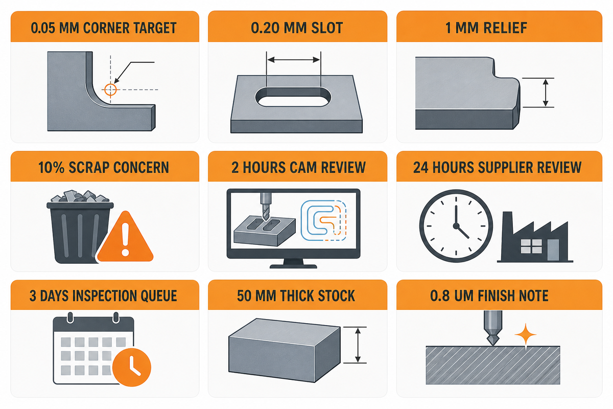
Use the numbers below as RFQ control fields, not universal capability promises. A supplier may quote tighter or looser limits after seeing geometry, stock thickness, machine condition, and inspection method.
For early DFM triage, mark any 0.05 mm corner target, 0.20 mm slot, 1 mm relief, 10% scrap concern, 2 hours of CAM review, 24 hours of supplier review, 3 days of inspection queue, 50 mm thick stock, or 0.8 um finish note as a feature that needs supplier feedback before release.
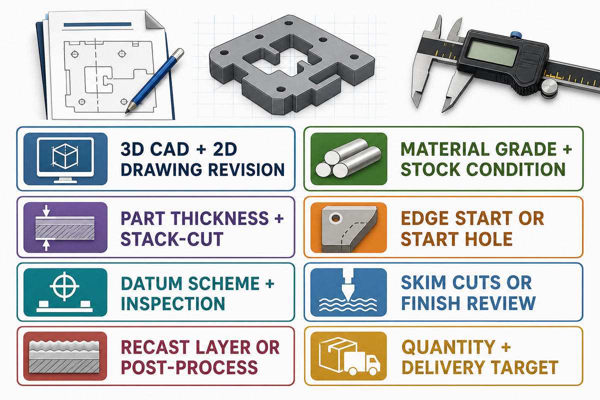
A good RFQ reduces guesswork. Instead of asking a supplier to “wire cut this part,” give the details that affect setup, path planning, and acceptance. This is especially important for prototype-to-production transitions, where a loose first quote can become a costly revision later.
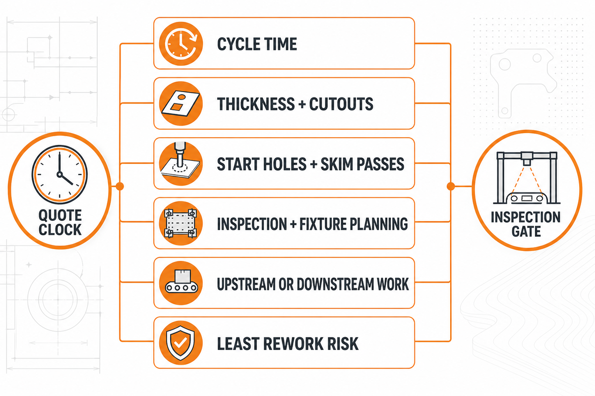
Cost is not set by material hardness alone. Cycle time, thickness, number of cutouts, start holes, skim passes, inspection, fixture planning, and scrap risk all influence the quote. A thin profile with one open edge may be simple. A thick plate with many closed windows, tight corner requirements, and finish controls will need more time.
Lead time also changes when the part needs upstream or downstream work. EDM may follow milling, thermal processing, grinding, coating, or inspection. For assemblies, the right question is not “Is this process slow?” but “Which route reaches the required edge, fit, and surface condition with the least rework risk?”
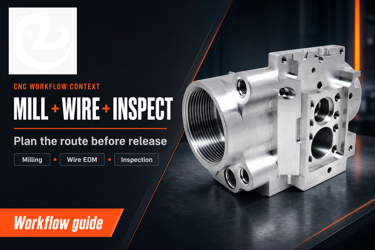
Lecreator positions Wire EDM alongside milling, turning, Swiss machining, and other precision manufacturing routes. For engineering teams, that matters because many parts are not pure EDM jobs. A part may be milled first, heat treated, wire cut for critical profiles, then finished and inspected.
When a drawing has both milled features and wire-cut profiles, send the full manufacturing context through a CNC machining service review rather than isolating one feature. The supplier can then choose the order of operations and flag tolerances that should be revised before purchase release.
Wire cut is the common manufacturing shorthand for Wire EDM. The process uses a moving electrode wire, dielectric fluid, and controlled spark energy to cut conductive material. It is different from hand wire cutting because no blade force is pushed through the material. In drawings and RFQs, saying Wire EDM is clearer than saying wire cut alone.
EDM is the broader family of discharge machining methods. Wire-cut EDM is the type that uses a traveling wire electrode to cut through profiles. Sinker EDM uses a shaped electrode to form blind cavities. Small-hole EDM can drill starter holes for later wire threading. Engineers should name the EDM type because each route has different access limits, setup needs, and inspection risks.
Start with geometry and material condition. If a mill can reach the feature, hold the size, and leave the required corner radius and finish, milling may be faster. Choose EDM when hardened material, thin walls, small internal radii, or low cutting force are more important than raw cycle speed. For a production handoff, compare the full route: rough milling, thermal processing, EDM, grinding, coating, and inspection. A process that looks slower at one operation can still reduce the total job risk if it avoids tool wear, distortion, or manual rework after hardening.
For normal shop use, it is for electrically conductive materials. That includes many steels, stainless steels, titanium alloys, nickel alloys, aluminum, copper alloys, and carbide grades. Non-conductive plastics and rubbers usually need another process unless a special conductive setup is involved.
EDM removes material by spark erosion rather than chip formation, so it can take longer on simple open shapes. Its value appears when conventional tooling would wear quickly, deflect, leave an unwanted corner radius, distort a thin section, or require too much finishing after hardening.