Supportive, Professional, Client-Focused Service
Get in touch with Lecreator Company
From prototypes to full-scale production, we’ve got you covered.


How to Solve Surface Finish Problems When Machining POM (Acetal/Delrin)
| As-Machined Ra (Standard) | Ra 1.6–3.2 μm (63–125 μin) |
| As-Machined Ra (Optimized) | Ra 0.4–0.8 μm (16–32 μin) |
| POM Melting Point | POM-H: 178 °C (352 °F) / POM-C: 166 °C (330 °F) |
| Recommended Cutting Speed | 120–150 m/min roughing, up to 450 m/min finishing |
| Typical Tolerance | ±0.05 mm standard, ±0.025 mm optimized |
| Post-Finish Options | Polishing (Ra 0.2 μm), Bead Blast (Ra 1.6 μm), Vapor Polish (Ra 0.4 μm) |
POM (polyoxymethylene) is one of the most commonly used engineering thermoplastics for precision machining – when surface finish goes wrong. Machined POM components that should be Ra 0.8 m come back at Ra 3.2 m or worse, with shining drag lines, whisker-like burrs and scratches, or tool marks visible to the naked eye — and that rougher surface disqualifies these cnc machined parts from assembly. Root causes are POM-specific and physics-focused, and the solutions differ inherently from metal machining operations.
This paper explains why CNC machined polyoxymethylene surface finish is disastrous, how to identify a defect, what cutting parameters and tooling will fix each one. Each Ra value and feed/speed recommendation is based on hard data and shop experience — not guesstimates. Whether you use CNC machining for POM homopolymer or copolymer POM, the principles are identical.
Most failures of POM machining finish trace back to thermal conductivity. According to polyoxymethylene data on Wikipedia, POM has a thermal conductivity of 0.31 W/m K. Compare that to aluminum at 205 W/m K – a 660x difference. When the machining operation wants to withdraw heat from the cutting zone, POM prefers to store heat in its workpiece instead.
That heat capacity deficiency causes three kinds of roughness failure:
It is the most common mistake for operators to make when shifting from machining aluminum or steel to POM. Despite the properties, feed and speed rates have to be lower for POM to keep its thermal heat in the cut zone. When combined with air spray cooling, the end result is always a better surface than high spindle rpms and flood cooling.

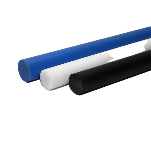
Not all POM grades are created equal. The amorphous (noncrystalline) nature of POM-H (also called Delrin, or homopolymer) and POM-C (called copolymer) impacts how a finished surface appears as a Ra number. Using a type of POM material that is not suitable for a finish critical part is a waste of time and effort.
| Property | POM-H (Delrin) | POM-C (Copolymer) |
|---|---|---|
| Tensile Strength | 76 MPa | 61 MPa |
| Melting Point | 178 °C (352 °F) | 166 °C (330 °F) |
| Crystallinity | ~80% | ~70% |
| Rockwell Hardness | M94 | M80 |
| Chip Formation | Shorter, crisper breaks | Longer, more ductile chips |
| Centerline Porosity | Significant in sections >50 mm dia. | Minimal to none |
| Chemical Resistance | Up to pH 9 | Up to pH 14 |
| Achievable Surface Finish | Ra 0.4–1.2 μm (higher hardness aids cutting) | Ra 0.4–1.6 μm (more forgiving parameters) |
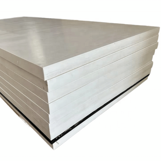
Unlike the rest of the world, North American POM-H (homopolymer, 50mm+ diameter rod) stocks often have a centerline porosity or white streak running through the molded or extruded dimensions. This porosity is created when gases forced from the melt when the POM cools that cannot escape the partlet congeal inside the extruded or molded shape. When machining POM-H rod through the center to machine a feature on complex POM parts, that errant porosity causes pitting that no finishing cut can remove. For a block or sheet application where machining through the center of large dims is critical, switch to POM-C at the design stage; no remedial finishing can remove porosity from precision machined parts. This is classified under ASTM D6778, the standard classification system for polyoxymethylene molding and extrusion materials.
Shop Floor machinists working with POM find that POM-C (copolymer, 12C lower melting point) is easier to get good finish appearance from. The difference can look drastic, and despite the lower melting point its lower crystallinity means less internal stress and warpage if the selected POM-C brand is properly machined. For a tight tolerance, lowest surface roughness POM component, POM-C often produces better post-machining dimensional stability with the desired surface finish.

In POM machining, surface roughness is governed by four factors with the following order of significance: cutting speed, tool geometry, feed rate and cooling technique. Proper ordering of these factors avoids the heat accumulation that tends to lead to most of surface quality problems.
| Parameter | Roughing | Finishing |
|---|---|---|
| Cutting Speed | 120–150 m/min (400–500 SFM) | Up to 450 m/min (1,500 SFM) |
| Feed Rate | 0.13–0.50 mm/rev (0.005–0.020 in/rev) | 0.10–0.30 mm/rev (0.004–0.012 in/rev) |
| Depth of Cut | 1.3–5.0 mm (0.050–0.200 in) | 0.13–0.50 mm (0.005–0.020 in) |
| Expected Ra | Ra 1.6–3.2 μm | Ra 0.4–0.8 μm |
| Parameter | Recommended Range |
|---|---|
| Cutting Speed | 60–75 m/min (200–250 ft/min) |
| Feed per Tooth | 0.05–0.25 mm/tooth (0.002–0.010 in/tooth) |
| Flute Count | 1–2 flutes (O-flute preferred for chip evacuation) |
| Strategy | Climb milling (reduces heat, produces better surface finish than conventional) |
| Expected Ra | Ra 0.8–1.6 μm with sharp carbide |
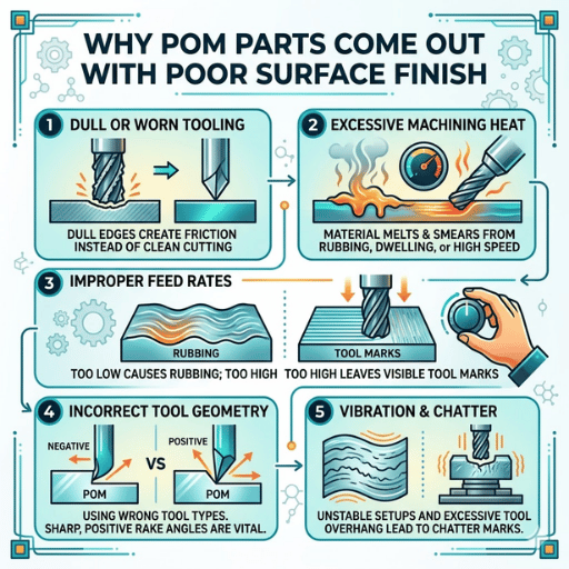
Tool geometry plays a more significant role in determining the POM surface quality than most operators anticipate. The appropriate rake and clearance angles discourage rubbing contact which causes localized melting.
📐 Engineering Note
Use uncoated, polished carbide tools for precision CNC machining of POM plastic. Use tools with a positive rake angle of 15-20, clearance angle of 10-15 and an up-sharp cutting edge. Use high-helix single flute or two flute end mills (O-flute design) to flush chips from the cut zone and avoid damage through re-cutting.
Do not use coated tools (TiN, TiAlN), as a film coating will rub on the low friction coefficient of POM (as low as 0.15-0.35) creating more heat rather than less. DuPont Delrin Design Principles for machining recommends polished tool faces to avoid chip adhesion.
Compressed air serves as the primary cooling method when running plastic CNC machining tools (apart from the injection moulding of the POM) is compressed air. The air blast blows the chips out of the cutting zone and also supplies adequate cooling so that the cutting temperature remains below 120 C (above which the POM begins to thermally decompose). Water-soluble fog coolant (to be water washed off after use) can be used for deep hole drilling, but avoided for prolonged use because continual contact with some of the chemicals in these coolants can cause stress cracking, especially around tight features.
Parameter priority when running a new POM machining: set cut speed (heat), set tool geometry (cut), set feed rate (chip load), then coolant (heat). If you tune from the bottom up—flood, then every step up—you’re likely to find chasing the workpiece’s surface finish rather than preventing it.
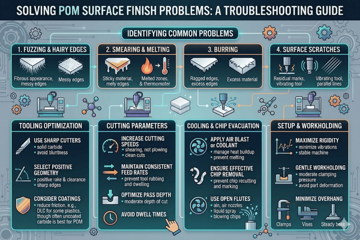
Every surface defect on a machined POM part can be traced back to one root cause; the correct defect type identification is the most rapid route to the correct solution; and avoids the common error of changing several machining parameters simultaneously.
What it seems to be: Lustrous areas on the machined surface with drag lines. The surface looks like it is semi-molten, not machined cleanly, and may have a minor degree of staining.
Root cause: The heat generated due to a high level of friction exceeds the softening temperature of the POM, that is 150-160 Deg.C, because the tools are dull or the spindle speed is very high, etc. This causes a severe temperature rise at the tool- work piece interface, due to POM’s low thermal conductivity.
Fix (a): Decrease spindle speed by 30-40%. Change to sharp uncoated carbide with polished flutes. Blow compressed air to the cut zone.
Typical result: Ra drops from 2.5-3.2 m to 0.6-1.0 m.
How it appears: Whisker-metal like edges on machined features. More noticeable after milling slots drilling holes. Burrs on POM are fibrous, not metallic, so they tend bend rather than break;
Root cause: POM’s high tensile strength and high ductility results in large amounts of plastic flow at the cutting edge without fracturing. Aggravated when operation is performed with duller tools, at toolless feeds (material bends before shearing) or in conventional mill direction.
Fix: Implement climb milling. Raise the feed rate to a high enough speed that the tool shears POM rather than pushes it. Use single-flute O-flute end mills when machining POM parts. For high volume production, cryogenic deburring and vibratory tumbling as a secondary machining process may be worthwhile.
What it looks like: regular gouging or scalloping marks found on flat or curved surfaces. Scallop size is directly related to the stepover between successive tooling passes.
Root cause: too high a radial stepover during finishing passes, culminating with consolidation passes with insufficient between-path overlap resulting in staccato toolpaths that don’t reflect the shape of the part. This is a programming problem, not an injection molding problem.
Fix: reduce the radial stepover during POM finish passes to 10-15% of the tool diameter. Infeed a dedicated light-deep cut finish pass (0.13-0.50 mm / 0.005-0.020 in). When sharp carbide is used at the correct speeds, a single pass can achieve a 3.2 m Ra standard finish down to a smooth finish of 0.8 m Ra without secondary operations.
What it looks like: machined POM parts that achieve surface finish specs directly from machine, but warp either side of dimensions within 24-48 hours in service causing the surface to drift out of print tolerances.
Root cause: internal internal stresses caused by the extrusion process release when asymmetric material removal allows the constrained part to relax. POM has very little moisture uptake (less than 0.2%) so moisture is not the cause – internal stress is.
Fix: explain CNC machining process sequences such that the machined POM parts are material-removal symmetric wherever possible; perform an internal stress-relief anneal of high-precision POM workpieces before final machining: raise POM-H to 160 C (POM-C to 150 C) in an oven with circulating air, hold for 30 minutes per 6 mm of wall thickness and cool at 10 C/hr. After annealing, allow 24 hours to stabilize the workpiece before finish machining.
What it looks like: random gouges and a non-uniform surface roughness that bears no relation to toolpath directions. Small POM particulates can be seen in the machined surface.
Root cause: long, stringy POM chips glide around the machining tool and come into contact with the workpiece again. Multi-flute tools with very small chip gullets tend to trap chips in the cut zone.
Fix: implement to a 1-2 flute tool with a high helix angle (30+) and mirror finished chip gullets. Blast air compressed through a wrench-blown nozzle at the cut zone to evacuate chips as they form. For turning operations implement chip-breaking geometry specific to thermoplastics. These changes almost always completely abolish re-cutting damage and it’s resulting Ra 0.8-1.6 m uniform surface texture across the POM workpiece, delivering the best surface quality achievable through accurate machining.
In cases where the as-machined finish on POM components fails to meet surface finish specifications, secondary surface treatments can be employed. Each method presents a trade-off in achievable Ra, machining cost and accuracy risks.
| Method | Achievable Ra | Best For | Risk Factor |
|---|---|---|---|
| Mechanical Polishing | Ra 0.2–0.8 μm | Sealing surfaces, bearings | Heat → dimensional change on tight tolerance parts |
| Vapor Polishing | Ra 0.2–0.4 μm | Complex geometries, optical clarity | Limited solvent compatibility with POM |
| Bead Blasting | Ra 1.6–3.2 μm | Uniform matte cosmetic finish | Does not reduce Ra below as-machined values |
| Tumble / Vibratory Finishing | Ra 0.8–1.6 μm | Small batch deburring + smoothing | Part geometry limits (fragile features may chip) |
A mechanical polishing operation introduces enough friction heat to distort precision machined POM parts out of tolerance. Allow for this by providing Ra 0.4-0.8 m on POM surfaces if your machine shop has tuned up the CNC machining parameters for the as-machined finish, or add an additional machining cycle after finishing, and hold the tolerances tight enough in the machining calculations to compensate for the additional cut. POM’s low surface energy also makes painting and coating the part difficult without plasma or chemical surface treatments to improve surface roughness values – a detail that often falls through the cracks in project planning.
Outside of the most demanding structural and dimensional tolerances, the as-machined surface finish of Ra 0.4-0.8 m suggested for a well-tuned set of CNC machining parameters is more than adequate. Plan to use additional machining steps in the event that non-functional finishing is required to meet the desired surface finish, or contouring the part in order to reach Ra below 0.4 m on the seal bore or running surface.

Indicating the required surface roughness on your POM part drawing requires referencing the appropriate measurement standard – which changed in 2021.
Since 2021, the international standard for measuring surface roughness is ISO 21920. Four standards (ISO 4287 – profile parameters, ISO 4288 – measurement instructions, ISO 1302 – drawing indication, and ISO 13565 – plateau-honed surfaces) combined into a single document that introduced new standards for evaluating surface finish for all measurement parameters and types. ISO 21920 introduces five Setting Classes (Sc1-Sc5) with preset filter types and evaluation length, which significantly reduces variance due to the operator in measurements. It applies internationally.
In the U.S., surface roughness is still regulated under ASME B46.1. This standard evaluation process uses the older, micrometer-based measurement system (x [in], the current conversion: 1 m = 39.37 in).
📐 Engineering Note
When indicating surface finish requirements on a POM drawing, always note the measurement standard (ISO 21920 or ASME B46.1), as well as the metric-based parameter (Ra, Rz, or Rq), and the evaluation length. Ra alone is insufficient data, as two POM surfaces with identical Ra 0.8 m can exhibit very different functional performance if one contains isolated deep scratches (high Rz), while the other exhibits predominantly uniform texture. For critical sealing, load-bearing, and aesthetic surfaces, Ra and Rz should be specified in conjunction.
Need precision POM parts with guaranteed surface finish specs?
This surface finish guide was thus written by Le-creator Technology’s Shenzhen-based engineering department based on 17 years of CNC machining experience for medical, electronics, and industrial machinery components manufacturing. Our CNC cutting parameters for Delrin, verified on an 80+ machine fleet when producing Ra 0.4 m plastic parts, demonstrate proving conditions for POM machining tool speeds and feeds, using a parameter data sample from the Curbell Plastics early de-contraction of a 75 mm+ POM rod sample. The centerline porosity and stress-relief annealing data were validated during serial production of homopolymer POM-H rod on our 15 tonne manufacturing yard for as-deformed round stock of 75+ mm diameter.