Supportive, Professional, Client-Focused Service
Get in touch with Lecreator Company
From prototypes to full-scale production, we’ve got you covered.


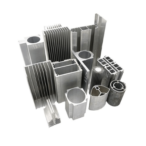
Alμminum E×trusion Machining — An Engineer’s Guide to Process, Materials, and Design
| Typical Alloys | 6061-T6, 6063-T5, 7075-T6, 5052-H32 |
| Post-Machining Tolerance | ±0.025 mm (±0.001 in.) achievable with CNC |
| Surface Finish (Machined) | Ra 0.4–1.6 μm |
| CNC Spindle Speed Range | 10,000–24,000 RPM (carbide tooling) |
| Cutting Speed (Carbide) | 200–400 m/min |
| Material Waste Reduction | 40–60% less than full-billet CNC machining |
| Key Standards | ASTM B221, ANSI H35.2, ISO 2768 |
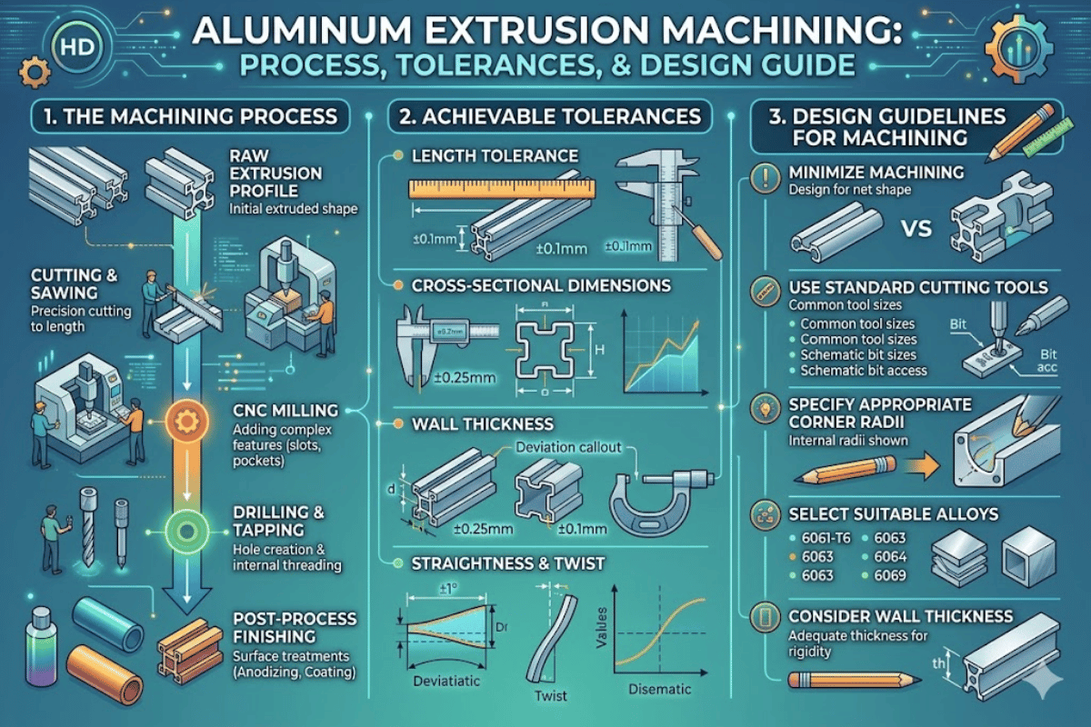
Aluminum extrusion machining combines two manufacturing stages into one production pathway: first, heated aluminum is forced through a shaped die to create a near-net-shape profile; then, CNC machining adds precision features that the extrusion process alone cannot produce. This hybrid approach reduces raw material waste, shortens cycle times, and delivers parts with tighter tolerances than either method achieves independently.
This guide covers the full workflow — from extrusion fundamentals and alloy selection through CNC operations, tolerance standards, and cost-saving design strategies. Whether you are specifying parts for an aerospace assembly or selecting profiles for an architectural rail system, the data and engineering parameters below will help you make informed machining and material decisions.
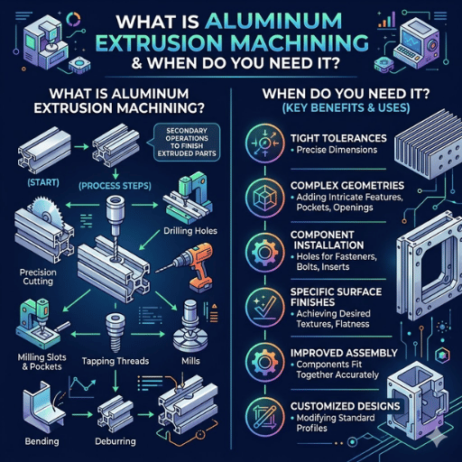
Aluminum extrusion machining is a two-stage manufacturing process. In the first stage, an aluminum billet is heated and pushed through a die to produce a continuous profile with a specific cross-sectional shape. In the second stage, CNC machining operations — milling, drilling, tapping, and cutting — add holes, slots, threads, and other features that the extrusion die cannot form.
The method works best when your part geometry starts with a consistent cross-section but requires localized precision features. Structural framing members with mounting holes, heat sinks with drilled attachment points, and aluminum extrusion machining services for electronic enclosure rails are all common applications of this approach.
✔ Advantages Over Full-Billet CNC
⚠ Limitations to Consider
If your part requires fewer than 50 units with no repeating cross-section, full-billet aluminum CNC machining may be more economical. Extrusion-plus-machining pays off when production volumes justify the die investment.

Six steps make up the manufactory flow path from raw aluminum to finished part. Each stage affects the mechanical properties and precision of part.
📐 Engineering Note
Always machine after aging, not before. Machining a pre-aged (W temper) extrusion introduces residual stresses that distort the part during subsequent heat treatment. One exception exists: rough machining before aging with 0.5–1.0 mm stock allowance for finish machining after aging. This two-stage approach is standard for aerospace components per AMS specifications.
After an aluminum profile departs from the extrusion press and attains the desired temper, cnc machining catalizes the profile from its polygon shape to a completed component. Every operation has a purpose and the composites needed are a function of your part geometry and tolerance requirements.
| Operation | Typical Tolerance | Spindle Speed | Best For |
|---|---|---|---|
| CNC Milling (3-axis) | ±0.05 mm | 10,000–18,000 RPM | Flat surfaces, pockets, slots |
| CNC Milling (5-axis) | ±0.025 mm | 12,000–24,000 RPM | Complex contours, angled features |
| Drilling & Tapping | ±0.05 mm position | 3,000–8,000 RPM | Through-holes, blind holes, threaded holes |
| Sawing / Cutting | ±0.5 mm length | 2,000–4,000 RPM | Length cutting, mitre cuts, notching |
| Laser Cutting | ±0.10 mm | N/A (beam) | Complex 2D cutouts, tube profiles, thin-wall slots |
| Deburring | N/A (edge quality) | Varies | Edge finishing, burr removal after drilling |
| Surface Treatment | +5–25 μm (anodize layer) | N/A | Anodizing (Type II/III), powder coating |
For CNC milling operations on aluminum extrusions, carbide end mills with polished flutes and high helix angles (40–45°) produce the best results. The polished flute surface prevents aluminum from adhering to the tool — a condition called built-up edge (BUE) that degrades both surface finish and dimensional accuracy.
Most aluminum milling uses 0.05-0.20 mm/tooth feed per tooth. Begins at the lower end and run larger as the part is fixtured, using machine rigidity guidelines. Same ranges of cutting speeds with a single-point carbide insert are used for the CNC turning operations on round extrusion profiles.
Applying steel-optimized tools on aluminum extrusions. Standard HSS tools intended for steel have less rake angles and unpolished flutes which weld the aluminum to the cutting edge. Result: poor surface finish, oversized holes, and premature tool failure. Always specify aluminum-specific carbide tooling with polished flutes.
Always specify aluminum-specific carbide tooling with polished flutes.

Not all types of aluminum alloys have good extrudability and each grade of alloy can have a very different machinability. Below is a comparison of four commonly extruded alloys with their mechanical properties and machining characteristics — all values at standard temper conditions.
| Property | 6061-T6 | 6063-T5 | 7075-T6 | 5052-H32 |
|---|---|---|---|---|
| Tensile Strength | 310 MPa | 186 MPa | 572 MPa | 228 MPa |
| Yield Strength | 276 MPa | 145 MPa | 503 MPa | 193 MPa |
| Hardness (Brinell) | 95 HB | 60 HB | 150 HB | 60 HB |
| Machinability | Good | Good | Fair | Fair |
| Extrudability | Moderate | Excellent | Poor | Good |
| Weldability | Good | Good | Poor | Good |
| Primary Use | Structural frames, fixtures | Architectural profiles, complex shapes | Aerospace, high-stress parts | Marine, corrosion-resistant applications |
‘6061 is often called ‘structural aluminum’ and 6063 used as ‘architectural aluminum’ through out the industry. There is an advantage to having a lower flow stress: 6063 produces more complex cross-sectioned profiles in extrusion and allows more complex shapes. Conversely, 6061 has more stringent machined tolerances due to hardness (95 HB as opposed to 60 HB).
For automotive components requiring moderate strength with good corrosion resistance, 6061-T6 is the standard choice. When the application demands maximum strength — such as aircraft wing spars or landing gear components — aerospace-grade alloys like 7075-T6 provide nearly double the tensile strength of 6061, though at the cost of extrudability and weldability. For marine or chemical exposure environments, 5052 aluminum offers the best corrosion resistance in the group.
📐 Engineering Note
By selecting 6063 for complex hollow extrusions that will be machined afterward, you should specify T6 temper rather than T5, if your machined profile demands tolerances better than 0.1 mm. Solution heat treatment in T6 raises the yield strength from 145 MPa to approximately 214 MPa, which reduces deflection during clamping and cutting – especially on thin-wall sections below 2.0 mm.

Two levels of tolerance control of the aluminum extrusion machining are made: the profile accuracy is fixed by the extrusion process baseline and cnc machining process is used to refine particular features to their final dimensions. Both are important to understand in order to specify tolerances correctly and not too expensively.
| Tolerance Type | Standard Range | Precision Range | Reference Standard |
|---|---|---|---|
| Extrusion cross-section | ±0.20–1.00 mm | ±0.10–0.50 mm | ANSI H35.2 |
| Straightness (per 300 mm) | 0.40 mm | 0.20 mm | ANSI H35.2 |
| Twist (per 300 mm) | 0.50° | 0.25° | ANSI H35.2 |
| CNC machined features | ±0.05 mm | ±0.025 mm | ISO 2768-m / ISO 2768-f |
| Hole position (CNC) | ±0.05 mm | ±0.025 mm | ISO 2768-f |
Surface finish is influenced by the manufacturing stage as well as any post-processing applied to the part:
| Processing Stage | Surface Finish (Ra) | Notes |
|---|---|---|
| As-extruded | Ra 1.6–3.2 μm | Die lines visible; acceptable for non-cosmetic surfaces |
| After CNC machining | Ra 0.4–1.6 μm | Finish depends on tool, speed, and feed parameters |
| After Type II anodizing | Ra 0.8–2.0 μm | Adds 5–25 μm oxide layer; slight roughening of machined surfaces |
The precision machining capabilities for aluminum extrusions at Le-creator maintain ±0.025 mm on machined features with CMM-verified inspection on every production run.
Having an ANSI B 4.2 compliant dimension of .025 across an entire extrusion profile when it is only relevant to the mounting holes will, for example, add 30-50% to the cost of machining. Concentrate tight tolerances to mating surfaces and important features. Maintain non-essential surfaces at the typical extrusion tolerance listed in ANSI H 35.2 – your designers, manufacturer and purse will be happy.
Aluminum extrusions machine faster than steel, but the combination of soft material, thin walls, and residual stresses from the extrusion process creates specific challenges. Here are five common problems and the cost-effective machining processes that solve each one.
1. Warping and distortion after machining
Cause: Residual stresses locked into the aluminum profile during extrusion. When machining removes material asymmetrically, the remaining stresses redistribute and the extrusion parts warp.
Solution: Request stress-relief stretching (0.5–2%) from the extruder before delivery. For tight-tolerance parts, use a phased approach: rough machining → stress relief anneal at 345 °C for 2 hours → semi-finish → finish machining. This five-step sequence improves efficiency in aerospace industry manufacturing.
2. Thin-wall vibration and chatter
Cause: Walls thinner than 1.5 mm are deflecting due to cutting forces. This gives rise to chatter marks and variation in dimension.
solution: Use as cast/ground, vacuum fixtures, or contoured support blocks which contact the entire profile surface. Use climb rather than conventional milling, depth of cut lower (e.g. 0.5-1.0mm per cut), and increase spindle speed to maintain chip load at the lower depth. Wall thickness should be no less than 1.0mm for stable machining.
3. Built-up edge (BUE) on cutting tools
Cause: Aluminum tends to weld onto tool surfaces at higher temperatures and lower rake angles.
Solution: Use carbide or diamond-coated tools with polished flutes and high helix angles (40–45°). Apply flood coolant or minimum quantity lubrication (MQL) with a cutting fluid designed for aluminum. Maintain cutting speeds above 200 m/min to minimize waste from built-up edge formation.
4. Chip evacuation in deep holes
Cause: Aluminum forms long, stringy chips, which get caught on the drill and clog up the hole.
Solution: Use peck drilling cycles with through-tool coolant delivery. Chip-breaker geometry on the drill point breaks continuous chips into manageable segments. For holes deeper than 3× diameter, reduce feed rate by 20% per additional diameter of depth.
5. Thermal deformation during long machining runs
Cause: Aluminum’s thermal expansion coefficient is 23.1 μm/m·°C — roughly double that of steel. Heat buildup during extended cuts causes the workpiece to grow.
Solution: Use flood coolant to maintain consistent workpiece temperature. For high-precision work, allow thermal equilibrium between roughing and finishing passes. CNC programs can include thermal compensation offsets based on measured temperature drift.

Cost in an aluminum extrusion machining project breaks down into three main categories: material, tooling, and machining time. Understanding where the money goes allows engineers to reduce per-part cost without sacrificing part quality.
Strategy 1: Design the extrusion to minimize post-machining processing. Every feature the die can form — channels, ribs, T-slots, screw bosses — is one fewer CNC operation. Work with the manufacturer during die design to push as much geometry as possible into the die shape. A well-designed die can eliminate 30–40% of machining operations and improve overall efficiency.
Strategy 2: Consolidate Machining Setups. Every time a operator re-fixtures a part, 15-30 minutes of non-cutting time is added. Design your part to have all features visible from a single or dual fixturing position. Where multiple faces are required, use a multitasking machining center capable of performing multiple machining operations.
Strategy 3: Specify tolerances only where they matter for component assembly and fit. As noted in the tolerances section above, applying precision tolerances globally rather than selectively inflates fabrication cost by 30–50%. Mark critical dimensions explicitly on the drawing and allow all other features to default to ISO 2768-m (medium tolerance class).
For any order size over 1000 units, a prototype run of 5-10 units costs less than the final extrusion die tooling and will test the profile and CNC machining program at once. At Le-creator, prototype parts can ship within 3-5 business days using stock extrusion profiles and CNC machining services.
Ready to start your aluminum extrusion machining project?
Le-creator runs over 80 CNC machines including 3-axis and 5-axis machining centers set up for aluminum extrusion processing. The tolerance data and machining parameters in this guide reflect production specifications verified across our ISO 9001-certified facility in Shenzhen. Surface finish values and alloy comparison data are cross-referenced with ASM International materials databases and the Aluminum Association’s published standards.