Supportive, Professional, Client-Focused Service
Get in touch with Lecreator Company
From prototypes to full-scale production, we’ve got you covered.


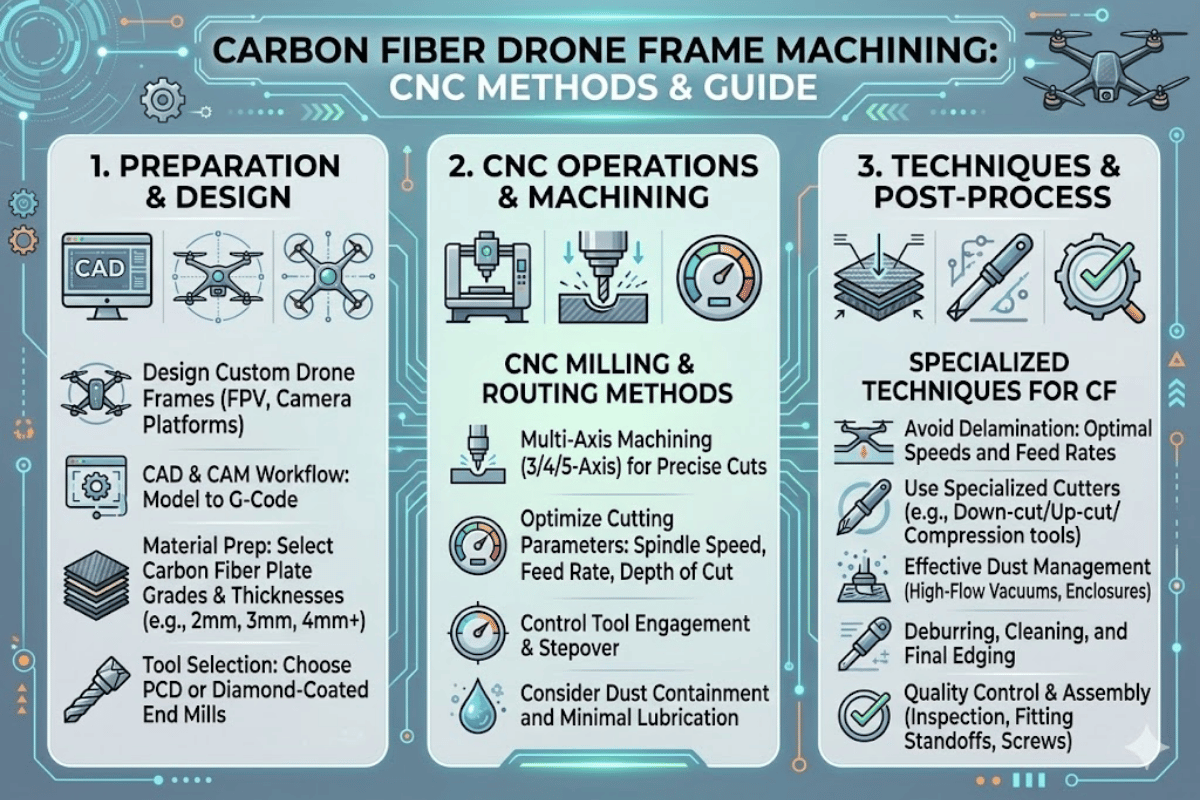
How Carbon Fiber Drone Frames Are CNC Machined — Methods, Materials, and Selection Criteria
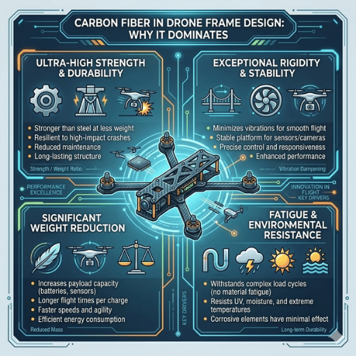
carbon fiber has been adopted as the de facto structure material of choice for high-performance drone frames. Its strength-to-weight ratio is five times greater than aluminum, a metric that, along with its stiff yet light weight, has made it the material-of-choice for FPV racing, industrial inspection devices, and agricultural UAVs. But the process of turning a large, uncured carbon fiber sheet into a finished drone frame calls for precise cnc machining knowledge—incorrect tooling or feed rates will delaminate plies, shatter edges and produce parts that will not even remain airborne.
This guide explains the cnc machining process of execution for carbon fiber drone frames: what techniques will and won’t work, which materials need to be specified, what tolerances and tolerability levels to expect, and how to select a machining partner who will not kill your prototype budget. Whether you’re an engineer drafting a custom drone frame, or a procurer concerned with settling for the wrong carbon fiber drone parts, this data has been culled from published material specifications, OSHA safety guidelines, and 17 years of production floor experience.
CFRP — carbon fiber reinforced polymer (‘cfrp’ or, in British, carbon fibre) do not hold a candle to those of its aluminum kin. A T700-grade carbon fiber sheet can stand 4,900 megapascals of strength at a density of only 1.55 grams per cubic centimeter. 6061-T6 aluminum peaks at 310 megapascals at a density of 2.70 grams per cubic centimeter. And yet, every competitive FPV racing drone frame has moved away from its aluminum-based material plate.
Additional benefits go beyond raw numbers. As bending and vibration damping materials, carbon fiber drone frames hold their form better under dynamic flight conditions than frames and aluminums. Irrespective of cyclic loading, carbon fiber composites do not sweat corrosion, fatigue, or buckle outside their temperature limits—which are often cited as 120-180 C for epoxy matrices.
The worldwide drone market hit USD 83.81 billion in 2025 and is projected to surpass USD 182.45 billion by 2033, based on numbers from Grand View Research. Lightweight material—carbon fiber composites inclusive—are recognized as primary factors for such forecasted growth. For instance, one documented case study displayed a 43-percent drop-off in weight going from aluminum to carbon fiber tube structure; an additional 16-percent increase in the frame design’s stiffness was also revealed. Our production site routinely witnesses drone clients reduce their total frame weight by 25-35 percent when switching to CNC-machined carbon fiber plates.
carbon fiber also conducts electricity. Depending on the placement of antennas and GPS modules on carbon fiber plates, signal attenuation causes range and navigational errors. Use GFRP for antenna mounting — its RF transparent and not nearly as heavy.
Unfortunately, not every cutting method will work with every material. Carbon fiber’s high abrasion capability produces dust particles, can cause delamination if excessive heat and pressure is imparted into the machining process, and generates highly abrasive particle dust. There are 4 common methods for carbon fiber cnc machining, but only 2 are recommended for production drone frames.
| Method | Tolerance | Heat Risk | Drone Frame Suitability |
|---|---|---|---|
| CNC Routing | ±0.025 mm | Moderate | Excellent — industry standard |
| Waterjet | ±0.10 mm | None | Good — zero heat-affected zone |
| CNC Milling (5-Axis) | ±0.025 mm | Moderate | Best for 3D contoured parts |
| Laser Cutting | ±0.05 mm | High | Poor — burns resin, causes delamination |
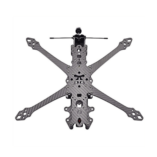
CNC routing remains the overwhelming process by far most common for drone frames, as most frames are cut from flat carbon fiber sheets in the 1.5-3.0 mm range. The machine profiles 2D shapes from sheet stock with no mold needed, to 0.025 mm tolerances at production speed. The vast majority of drone frame geometries are handled by 3 axis CNC router. 5 axis CNC milling is only used for contoured 3D enclosures or parts with machining from multiple angles in a single fixturing step; it adds hundreds to thousands more programming and machine cost that flat drone plates don’t justify
Avoid laser cutting on carbon fiber at all costs. Concentrated heat degrades the epoxy resin matrix, causes charring along cut edges and releases unwanted toxic fumes. When a zero heat-affected zone is necessary, waterjet cutting remains a viable alternative when compared to the slower, more expensive per part CNC routing
Prototyping with carbon fiber, our engineering team has discovered the following parameter ranges seem to provide predictable results when working across T300 through T800 grade sheets:
carbon fiber is not always the appropriate answer. Knowing where each material belongs, prevents overspending (and overengineering) on the drone frame projects. Below is a table based on published material property data from ASM International, composite datasheet schedules.
| Property | CFRP (T700) | 6061-T6 Aluminum | GFRP (E-glass) | Nylon PA6 |
|---|---|---|---|---|
| Tensile Strength (MPa) | 4,900 | 310 | 500-1,200 | 70-85 |
| Density (g/cm3) | 1.55 | 2.70 | 1.80-2.10 | 1.13 |
| Cost (USD/kg) | $30-90 | $2-5 | $10-25 | $3-6 |
| Vibration Damping | Good | Poor | Moderate | Very Good |
| CNC Machinability | Difficult (PCD tools) | Excellent | Moderate | Good |
| Failure Mode | Brittle fracture | Ductile bend | Bend before break | Flex/deform |
Choosing to specify carbon fiber at every drone component, when glass fiber is the better choice in our specific parts. GFRP has 2/3 the cost of CFRP, is more RF-transparent (critical in antenna plates), and tends to bend before it shatters; an advantage in crash-prone applications in beginner FPV quads. Use machined carbon fiber on structural and arm plates, where you need stiffness. Use glass fiber where you need antenna mounts and replaceable bumper plates.
Aluminum remains a reasonable choice for large commercial drone frames where carbon fiber cost becomes prohibitive, and repairability is desirable Aluminum bends and can be straightened, CFRP shatters with no warning deformation. Nylon (PA6/PA12) is relegated to nonstructural parts like landing gear, camera mounts, nose cones, where flex absorption is more desirable than rigidity.
Selecting a well-designed carbon fiber drone frame accounts for the machining constraints near the outset of the CAD phase. Ignoring these constraints results in delaminated edges, cracked mounting holes and parts that appear correct under color camera, but snap under flight loads. Here is our design-for-manufacturability drone frame preparation checklist.
| Thickness | Typical Drone Application |
|---|---|
| 1.0 mm | Top plates for micro drones, camera mounting plates |
| 1.5 mm | Arms and side plates for 5-inch racing quads |
| 2.0 mm | Standard bottom plates for 5-inch FPV frames |
| 2.5mm | Heavy-duty bottom plates, 7-inch long-range arms |
| 3.0-6.0 mm | Industrial/commercial UAV structural components |
T700 is today’s industry standard for high strength drone frames. It gives 4,900 MPa tensile strength compared to T300’s 3,530 MPa – a jump of 38.8% – while retaining higher final elongation (2.1% versus 1.5%). That extra ductility allows T700 frames to absorb crash impacts without imploding as readily as T300. T800 provides higher stiffness 294 GPa versus 230 GPa modulus but is brittle on its own. Some sections break in T800 alone, so a handful of manufacturers lay T800 as inner plies, with T700 outer plies to get the best properties out of T800 frames for the cheapest prices.
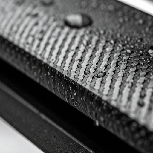
In cnc machining operations, ignoring fiber orientation relative to the cutter matters. Twill weave is common for drone frames because it shares load across multiple directions. When providing parts for cutting from a twill-weave carbon fibre sheet, orient your CNC toolpath such that you do not have a sustained cut parallel to one fiber direction; the load and resulting delamination risk will be forced into a line across the sheet.
Care must be taken when using carbon fiber for any part. It dulls cutting tools faster than almost any other material, produces dangerous conductive dust, and proved in testing to fail in complex, uncontrollable ways while the part is still loaded on the table. Here are the three most wasteful problems that happen during CNC carbon fiber cutting.
Delamination occurs when the cnc forces are greater than the interlaminar shear strength of the resin that holds the carbon fiber plies together. Dull tools, high feed/ cutting speeds, and heat build-up can soften and weaken the resin. To avoid it:
– use sharp PCD or diamond coated tools
– run the spindle 18,000- 25,000 RPM
– use supporting plates on the exit side of all through-cuts
carbon fiber is extremely abrasive. Back in the shop, carbide tools are dull after minutes of cut time; PCD (polycrystalline diamond) end mills last 20-25x longer in our shop. The cost benefits are clear: a PCD end mill can cost 3-5x than a carbide end mill up front, but can cut 14,000 linear inches of carbon fiber before it needs replacing. After tracking a 60% reduction in tooling costs per part over six months, in this shop we switched to PCD cutting tools for our carbon fiber CNC runs.
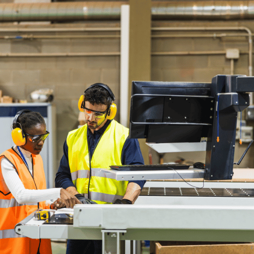
Machining carbon fiber results in fine airborne particles in the 5-7 micron range – so small they can penetrate the lower respiratory system. According to the Occupational Safety and Health Administration (OSHA), carbon fiber dust is regulated as Particulates Not Otherwise Regulated (PNOR) where permissible exposure limits (PEL’s) are 15 mg/m3 for total dust and 5 mg/m3 for respirable fractions. The National Institute for Occupational Safety and Health (NIOSH) recommends no more than 10 mg/m3 total and 5 mg/m3 respirable.
In addition to inhalation hazards, conductive carbon dust particles can create a short in electronic equipment produced in the workshop. Each shop doing any CNC carbon fiber cutting requires enclosed machining with dedicated dust extraction, water-based machining (flood coolant to suppress particles) and personal protective equipment.
A study (International Journal of Advanced Manufacturing Technology) indicated that Fiber orientation angle has a great influence on the cutting forces. Comparing a 135° fiber angle to a 45°, the former offers the maximum tangential forces and the worst delaminating risk, while the later offers minimum forces and relatively clean surface finish. Wherever it is possible with your drone frame design, make sure to orient your fibers at the minimum axial angles, i.e. at 45°.
It will significantly reduce tool wearing and the risk of delamination.
Not all CNC shops are able to accommodate carbon fiber drone parts. Carbon fiber requires dedicated tooling, an efficient dust extraction set up and an operator familiar with carbon fibre composite performance. Below an assessment framework by itself on what makes good suppliers versus shops that will cost you a pretty penny in prototyping.
Le-creator leverages 80+ state-of-the-art CNC machines with dedicated carbon fiber machining capability, 98%+ first pass yield, 100% outgoing quality inspection of each part. Le-creator offers 17 years of precision manufacturing experience to 1,000+ aerospace, medical and industrial customers. Our team offers rich machining know-how at your service in each drone frame project; please browse through Le-creator’s carbon fiber capabilities to learn about how we handle custom carbon fiber products from prototype to production.
Watch out for a shop with no questions about your grade of material, weave style, and tolerance requirements asking for a quote for carbon fiber machining. If they have them for CFRP as they would for alum, you will see your parts.
— Le-creator Engineering Team
cnc machining is one of the only manufacturing processes to function at both prototype and production scale for drone frames without process modifications. It has no molds to construct, no tooling investments, and design revisions are a CAD file modification away. This is the reason most of the drone frames manufacturing companies—even in volume—use CNC and not compression molding.
| Stage | Quantity | Typical Lead Time |
|---|---|---|
| Prototype | 1-5 pcs | 3-7 business days |
| Small batch | 10-50 pcs | 5-10 business days |
| Production run | 100-1,000+ pcs | 7-15 business days |
Compression molding is only cost effective if you are producing more than around 500-1,000 units—and even then, only if the design is locked down. Mold tooling for a carbon fiber drone frame runs $5,000-$50,000 dependent on geometry complexity. For drone builders attempting to iterate the frame design (the vast majority of RC and open source FPV projects), cnc machining is the cheaper route, as any design iteration involves no additional expense beyond updating the CAD file.
When you are ready to scale find a machining partner that supports batch nesting — placing many parts on one sheet carbon fiber panel. Do this to minimize material waste and to bring down the cost per part. Get a feel for how Le-creator machines carbon fiber parts for drone builders, across prototype and production volumes.
Send us your CAD for a free quote. Prototype parts are shipped in 3-7 work days.
This brief was written by the team of engineers working at Le-creator a dedicated cnc machining entity with 17 years of innovation in producing high-quality custom carbon fiber parts for drone, aerospace and industrial equipment clients. The property data contained herein stems from publicly accessible Toray datasheets, ASM International databases, and peer-reviewed papers. The machining data and DFM suggestions we offer are based on our production accumulated data across thousands of carbon fiber drone frame parts.