Supportive, Professional, Client-Focused Service
Get in touch with Lecreator Company
From prototypes to full-scale production, we’ve got you covered.


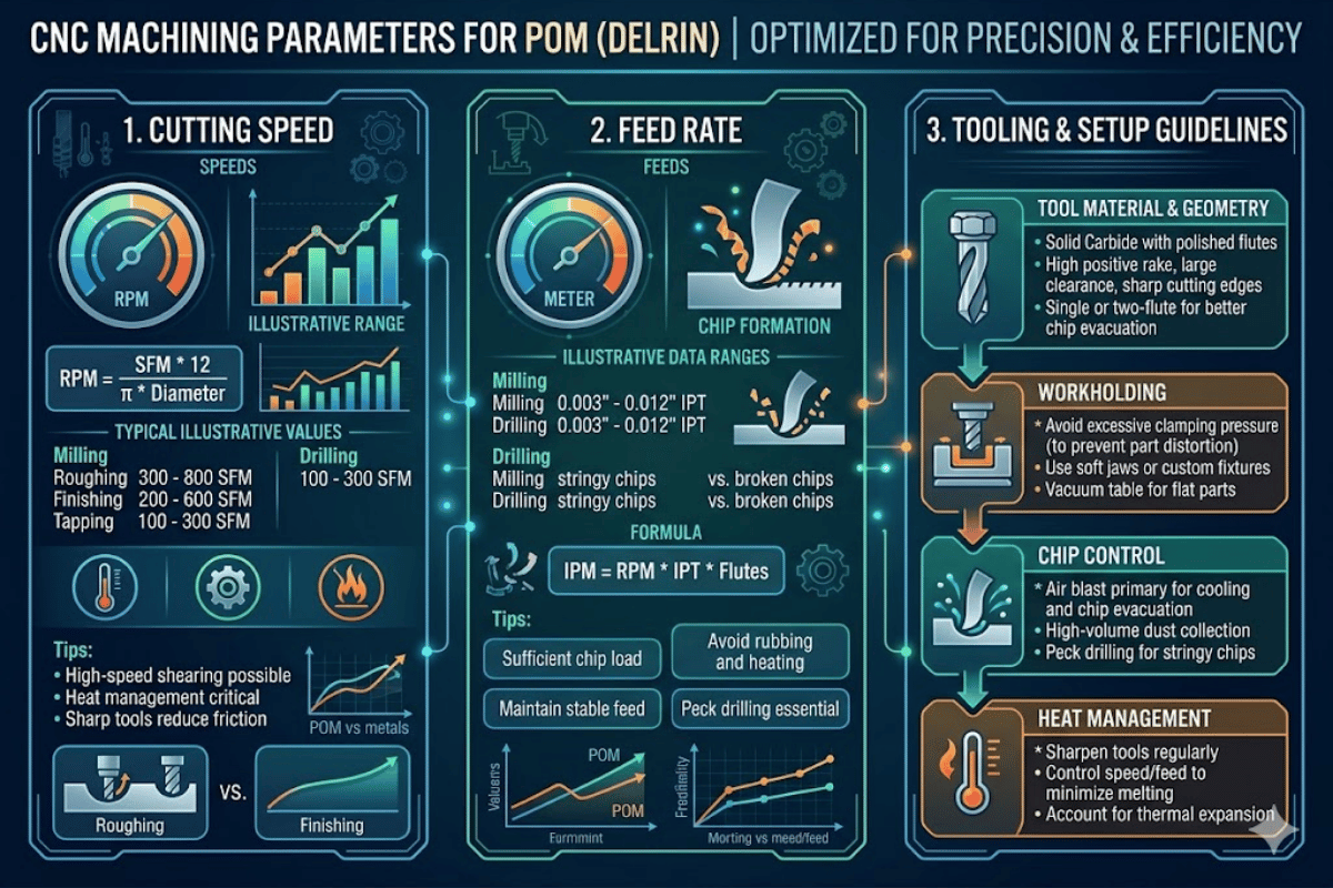
CNC Machining Parameters for POM — Speeds, Feeds, Tools and Tolerance Data
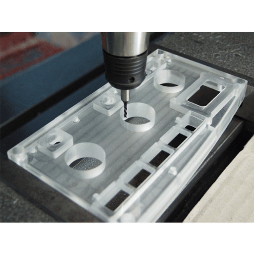
Polyoxymethylene (POM) is one of the most machinable engineering plastics you can expect to find on any shop floor. This POM machining guide is compiled from actual cut parameters, tool selections and tolerance ranges that matter when you program a POM plastic part on a CNC plastic milling or turning center—no theory, only numbers you can punch into the controller.
| Material | POM (Polyoxymethylene / Acetal / Delrin) |
| Typical Cutting Speed | 150–500 m/min |
| Feed Rate (Milling) | 0.05–0.25 mm/tooth |
| Feed Rate (Turning) | 0.05–0.30 mm/rev |
| Achievable Tolerance | ±0.02–0.10 mm |
| Surface Finish (Ra) | 0.4–1.6 μm (as-machined) |
| Max Service Temp | 90–100 °C continuous / 140 °C short-term |
| Preferred Tool Material | Uncoated carbide / PCD |
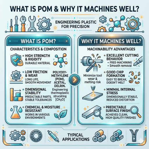
A full name for POM, polyoxymethylene can be purchased by many traders, such as Delrin (DuPont) and Ultraform (BASF)—semi-crystalline engineering plastics, in which the crystallinity is as high as 75%. It is such a crystalline nature that brings this POM material its typical strength, noting that: the tensile strength = 60-70 MPa, the coefficient of friction coefficient= 0.20-0.35 and the dimensional stability is tightly as time goes on.
Basically, there are two grades of POM: homopolymer POM (POM-H) and co-polymer POM (POM-C). Of the two, POM-H has a higher stiffness and tensile strength—roughly 5-10% more than POM-C—for the machining work of gear and structure components. POM-C is inferior to POM-H in these aspects, but throughly better for its chemical resistance, thermal conductivity during machining and reduced Centreline porosity susceptibility. For workpieces with tight tolerances, the latter is preferred.
Apart from having a lower coefficient of moisture absorption (less than 0.2%, compared with 1-2% of nylon fibers), POM exhibits excellent dimensional stability for shop floors—whether dry or humid. When coupled with its naturally good lubricity and notable resistance to solvents, alcohols, weak acids and fuels, the mechanical properties of POM material make it suitable for precision parts in automobile components, medical instruments and food processing machinery.
Material is machined with process parameters to produce both a dimensionally stable and smooth part or a warped one from heat generated. The roughing and finishing tables are provided separately—most guides just give the former, but the latter counts for machining a POM workpiece with tight tolerance.
| Parameter | Roughing | Finishing |
|---|---|---|
| Cutting Speed | 200–400 m/min | 300–500 m/min |
| Feed Rate | 0.15–0.30 mm/rev | 0.05–0.12 mm/rev |
| Depth of Cut | 1.5–3.0 mm | 0.3–0.8 mm |
| Rake Angle | 6°–10° positive | 6°–10° positive |
| Parameter | Roughing | Finishing |
|---|---|---|
| Cutting Speed | 150–250 m/min | 250–350 m/min |
| Feed per Tooth | 0.10–0.25 mm/tooth | 0.05–0.10 mm/tooth |
| Axial DOC | 2.0–4.0 mm | 0.5–1.5 mm |
| Spindle Speed | 4,000–6,000 RPM | 6,000–8,000 RPM |
| Parameter | Recommended Value |
|---|---|
| Spindle Speed | 1,000–2,500 RPM |
| Feed Rate | 0.05–0.15 mm/rev |
| Point Angle | 118° (standard twist drill) |
| Peck Cycle | Required for L/D > 3:1 |
📐 Engineering Note
A study printed by MDPI Metals in 2023 found that accurate parameters for POM-C turning over a PCD tool reduced total machining time by 44%. The work employed RSM and a face-centered CCD experimental design, with the goal to harmonize surface roughness with workpiece deflection and good chip formation.
In general, compressed air suffices to cool off POM machining. Since POM absorbs practically no humidity, it is also possible to use water-based coolant for mass production without alteration of workpiece dimensions—an issue that cannot happen when using carbide-grit-filled thermoplastics like nylon where the sudden coolant flow may result in material swelling.
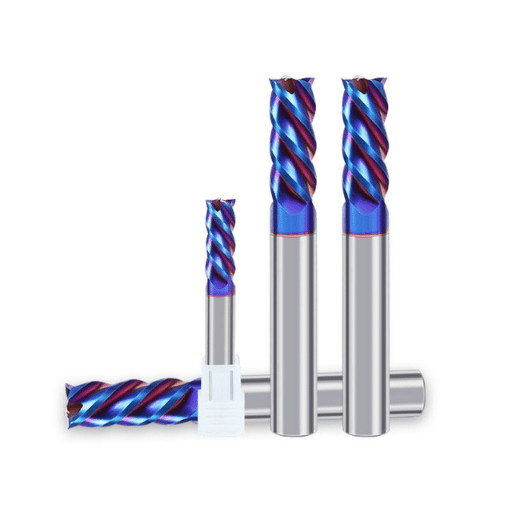
To choose a tool and tool geometry for POM will firstly depend on the batch size and surface roughness that you expect. POM typically performs better than most reinforced plastics or metals with lower tool wear on the CNC machine, thanks to its softness, but it also is delicate to have burrs or melted parts if the wrong tool geometry is used.
| Tool Material | Best For | Typical Tool Life | Surface Finish |
|---|---|---|---|
| HSS (High-Speed Steel) | Prototypes, short runs | 500–2,000 parts | Ra 0.8–1.6 μm |
| Uncoated Carbide | Production volumes | 5,000–15,000 parts | Ra 0.4–0.8 μm |
| PCD (Polycrystalline Diamond) | High-volume, tight tolerance | 50,000+ parts | Ra 0.2–0.4 μm |
| DLC-Coated Carbide | Reduced friction applications | 10,000–20,000 parts | Ra 0.4–0.6 μm |
Two-flute end mills work much better than four-flute sets when working with POM. The unitary larger cutter GFI elements and deflects chips far quicker, resulting in fewer accumulations of re-cut melted Plastics. Using a positive rake angle of around 6-10 degrees boosts the machine’s ability to preplan the shear rather than forces the material—hence your tool—pushing—thus improving process quality and extending tool life.
For precision machined POM parts, carbide tools are the cheapest and most effective option. Save PCD for jobs requiring sub-micron surface finishes, or where the tooling investment can be amortized across medium-high batch quantities.
POM tends to yield one of the best as machined surface finishes of any engineering plastics. With sharp carbide tooling and a conservative feed rate, 0.4-0.8 Ra is possible directly from the CNC without polishing.
| Feature Type | Standard Tolerance | Tight Tolerance | Notes |
|---|---|---|---|
| Linear Dimensions | ±0.10 mm | ±0.02 mm | Requires annealing + climate control |
| Bore Diameter | ±0.05 mm | ±0.02 mm | Ream after drilling |
| Flatness | 0.10 mm/100 mm | 0.05 mm/100 mm | Symmetric material removal critical |
| Surface Roughness | Ra 0.8–1.6 μm | Ra 0.2–0.4 μm | PCD tooling for best finish |
Coupled with zero tolerance-machined fixturing and stress-relief annealing, tolerances between 0.02 mm can be held. Researchers Pinisetty and Redner demonstrated that for POM, feed rate and nose radius dominate surface roughness, with depth of cut holding a secondary influence.
A reputation for easy machining means it is always a surprise when any of three problems catch operators off guard, especially metal machinists new to plastics. Each stems from a specific trait of the POM machining process and has an appropriate solution.
| Problem | Root Cause | Solution |
|---|---|---|
| Warping after machining | Residual stress from extrusion/molding released by material removal | Anneal between rough and finish passes; remove material symmetrically |
| Burr formation on edges | Dull tool edge or excessive dwell at exit points | Maintain sharp tools; use climb milling; program exit paths to avoid dwell |
| Cracking (especially POM-H) | Stress concentration at sharp internal corners; centerline porosity in homopolymer POM | Add fillet radii ≥0.5 mm; switch to POM-C for thick-wall parts; anneal before final machining |
📐 Engineering Note — Annealing Protocol for POM
Anneal at 140-150 C (10-20 C below heat distortion temperature) to minimize residual stresses. In an oil bath, hold for 40-60 minutes per 5 mm wall. In a room temperature air bath, hold 20-30 minutes per 5 mm wall. Allow to cool to room temperature fully before machining or reintroducing stress. Avoid forced cooling at the annealing step; reintroduced residual stresses would offset the dimensional benefits. Schedule after rough machining or during intermediate finishing stages. This step matters most for POM features requiring tolerances finer than 0.05 mm.
From a chemical standpoint, POM begins degrading above 230 C and simultaneously emits formaldehyde. If machining during hot chip removal, proper ventilation should be maintained at the operator station. Cases of excessive heat generation at the work zone due to unbaffled chips and concentrated cutting zone friction heat is well documented.
Optimum application selection between POM and other engineering plastics depends on what operating conditions are most important to the application and the process. Below, a table compares the actual property values (values for “good” are also listed to illustrate that there is no take-for-granted correlation) of each.
| Property | POM (Acetal) | Nylon (PA6/66) | PEEK |
|---|---|---|---|
| Tensile Strength | 60–70 MPa | 70–85 MPa | 90–100 MPa |
| Friction Coefficient | 0.20–0.35 | 0.35–0.45 | 0.35–0.40 |
| Max Continuous Temp | 90–100 °C | 80–100 °C | 250 °C |
| Moisture Absorption | <0.2% | 1.0–2.5% | <0.1% |
| Machinability | Excellent — clean chips | Good — tends to smear | Good — higher cutting forces |
| Relative Material Cost | 1.0× | 0.7–0.9× | 15–20× |
For applications where dimensional stability and friction coefficient are most critical, POM is the best. POM does not absorb water and change dimensions, like Nylon will, by 0.5-1.0% in an otherwise humid environment. POM also loads easier and equilibrates quicker than PEEK under high-temperature / chemically harsh environments, but costs 15-20 /kg. For CNC machined parts and the applications they are most suitable for, POM will outperform composites or other plastics below 100 C in cost, machinability, and performance.
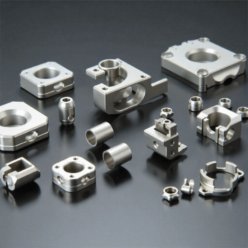
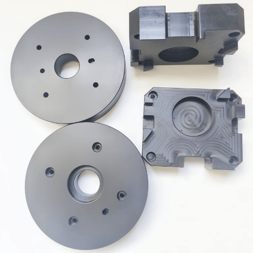
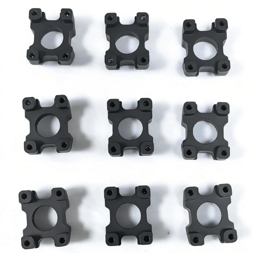
POM’s combination of low friction and the mechanical properties of this plastic material make it ideal for self lubricating applications where excess weight or excess material would be a hindrance to a product. The following industries make up the majority of the machined POM market:
Automotive: Fuel system clips, seat belt guide bushings, window regulator gears, and interior mechanism components. POM is used here because it resists lots of cycles, and being exposed to room temperatures, and long-term exposure to automotive fluids, even repeatedly over many cycles without decomposition.
Medical Devices: Inhaler bodies, surgical instruments handles, medicament delivery pump parts. Because POM homopolymer conforms to FDA 21 CFR 177.2480, use in contact with food, extractives are limited to 0.5mg/in and formaldehyde content is below 0.0050percent by weight. POM copolymer is separately regulated under 21 CFR 177.2470.
Food Processing: Conveyer guides, packing machine wear strips, and valve seats. POM’s proven endurance in the wet environment of food processing, coupled with FDA-compliant grades, makes POM an excellent choice for food contact machinery.
Industrial Equipment: Plain bearings, gear mechanisms, valve bodies, and pump impellers. POM’s low coefficient of friction (0.20-0.35) enables some bearing applications to be run without lubrication – cutting down on maintenance frequency and preventing contamination of clean environments.
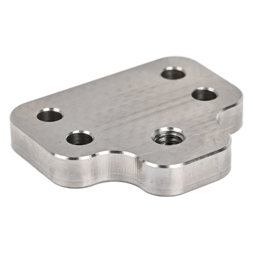
For all of these end markets, POM machined to custom specifications by CNC not only provides great tolerances and amazing repeatability, but outperforms injection molding in the 5,000 pieces-per-order range.
Long-term service 90-100 C. Short-term exposure 140 C. Above 230 C POM decomposes and releases formaldehyde – adequate through ventilation is necessary during high-speed machining to prevent local overheating.
Consider PEEK over 120 C, though at 15-20 the material cost.
Need precision POM parts machined to your specifications?
This guide has been compiled by the engineering department at Le-creator, a Shenzhen-based CNC machining company with 17 years of production experience working with POM, PEEK, nylon, and over 40 other engineering plastics. The milling ranges listed in this article have been cross-checked against existing research published by MDPI and Springer, as well as the data we obtain from operating over 80 CNC machines each day on polymer stock.