Supportive, Professional, Client-Focused Service
Get in touch with Lecreator Company
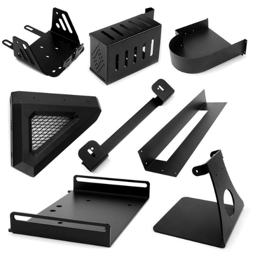
From prototypes to full-scale production, we’ve got you covered.


Sheet Metal Laser Cutting Tolerances: A Complete Guide for Engineers
Sheet metal laser cutting tolerances are what determines if a part of yours fits, works, and is accepted by a customer. The standard sheet laser cutting tolerances should be expected to be in the range of 0.005 inches -0.010 inches (0.13-0.25mm) on most materials and thicknesses. Fiber laser cutting systems give the tightest sheet laser cut tolerance of 0.002 to 0.003 inches on a light gauge stainless steel or mild steel sheet. What follows is a sheet laser cut tolerance data table filtered by material and thickness, a comparison of fiber laser vs CO2 laser accuracy, an overview of the factors that influence how tight or loose your sheet laser cut tolerance is, and sheet material design recommendations to manage sheet metal fabrication costs.
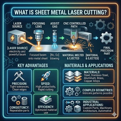
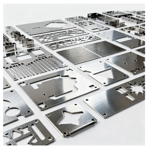
Sheet metal laser cutting is a modern, computer numerical control (CNC), thermal sheet metal cutting process that has a laser focus melt, burn, vaporize, or blow through your sheet metal along a programed path. An assist blast of nitrogen, oxygen, or compressed air is directed through the laser cutting nozzle to clear molten material from the kerf and keep it from oxidizing the cut face.
In the sheet metal laser cutting marketplace, two laser sources are popular. A fiber laser produces light at a 1.06 m wavelength that is transmitted through a flexible fiber to the cutting head,. In a gas mixture of carbon dioxide, nitrogen, and helium, a CO2 laser produces light at a 10.6 m wavelength. Fiber laser cutting technology has increasingly overtaken CO2 systems for sheet metals under 12mm thick since it can cut more quickly, run more economically, and process reflective metals such as aluminum, copper, and brass without problems with beam backreflection.
Computer Numerical Control (CNC) sheet laser cutting machines use a rigid CNC controller to execute two-dimensional profile cut paths, usually imported through a DXF or DWG drawing file. Large format fiber laser cutting machines equipped with 3-6 kW of available cut power will cut mild steel as thick as 20 mm, stainless steel as thick as 15 mm, and aluminum as thick as 12 mm. The placement accuracy of a well-maintained, regularly inspected machine is 0.001 inch, while the repeatability of the same machine with the same program is 0.0005 inch over the entire length of travel. When compared to plasma cutting, the laser delivers a much smaller kerf (0.1-0.4 mm vs 1.5-4 mm for plasma), greater precision, and a very nice edge quality that often negates secondary deburring.
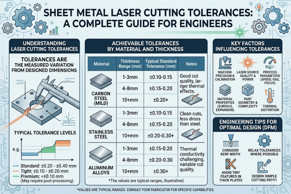
The key to sheet laser cut tolerance is material and thickness. Tolerance data for the sheet alloys listed below, cut on a modern fiber laser system at standard calibration, is shown in the table. All tolerances are what may be dimensional control on cut features hole diameter, slot width, and part outline, not machine location accuracy and repeatability.
| Material | Thickness Range | Typical Tolerance | Notes |
|---|---|---|---|
| Mild Steel | 0.5–3 mm | ±0.1 mm (±0.004″) | Fiber laser; nitrogen or oxygen assist |
| Mild Steel | 3–12 mm | ±0.2 mm (±0.008″) | Thicker materials require slower feed rate |
| Mild Steel | 12–25 mm | ±0.3–0.5 mm (±0.012–0.020″) | CO2 or high-power (10 kW+) fiber |
| Stainless Steel | 0.5–3 mm | ±0.05–0.1 mm (±0.002–0.004″) | Best cut quality; nitrogen assist preferred |
| Stainless Steel | 3–8 mm | ±0.1–0.2 mm (±0.004–0.008″) | Nitrogen for oxide-free edge |
| Aluminum | 0.5–3 mm | ±0.1 mm (±0.004″) | Fiber laser preferred; reflective surface |
| Aluminum | 3–10 mm | ±0.15–0.25 mm (±0.006–0.010″) | High thermal conductivity widens HAZ |
| Brass | 0.5–3 mm | ±0.1 mm (±0.004″) | Fiber laser only; CO2 beam reflects |
| Copper | 0.5–3 mm | ±0.1–0.15 mm (±0.004–0.006″) | Needs high power (4 kW+); narrow process window |
On a 10:1 scale, tolerances on thick mild steel can be as much as 0.02″ while sheet stainless steel can be cut to 0.002″. All sheet laser cut tolerances are highly dependent on material thickness, since as material gets thicker, more energy must be delivered to achieve the cut, the resulting kerf is wider, and the heat affected zone increases with it, all of which means looser tolerance on the finished part.
If he is running a laser cut part on his milling center prior to machining the stainless steel or aluminum, he will want the as-cut diameter tolerance stated so he can account for it in his stock subtraction.
In addition to differences in wavelength, beam delivery and interaction with the metal, fiber lasers and CO2 lasers have different tolerance capability, cut quality and cost per part. The table below summarizes the comparison for sheet metal.
| Criteria | Fiber Laser | CO2 Laser |
|---|---|---|
| Wavelength | 1.06 μm | 10.6 μm |
| Positional Accuracy | ±0.002″–0.003″ | ±0.004″–0.005″ |
| Repeatability | ±0.001″ | ±0.002″ |
| Cutting Speed (thin gauge) | 2–3x faster than CO2 | Baseline |
| Beam Diameter | ~25 μm focused spot | ~75–100 μm focused spot |
| Kerf Width | 0.1–0.2 mm | 0.2–0.4 mm |
| Reflective Metals | Cuts brass, copper, aluminum | Risk of back-reflection damage |
| Thick Steel (>20 mm) | Requires 10 kW+ systems | Strong performer up to 25 mm |
| Operating Cost | 30–50% lower (electrical efficiency) | Higher (gas consumption, mirrors) |
Fiber laser cutting enables a smaller beam diameter and narrower kerf than CO2 cutting, which translates into tighter tolerances and less scrap. The 1.06 m wavelength is absorbed more effectively by metals, so fiber lasers provide faster piercing and cutting performance on thin-to-medium gauge sheet metal. This is why most new laser shops targeting sheet metal business will buy a fiber laser cutting system.
It is true that CO2 lasers still have an advantage in two areas: performance on thick steel above 20 mm thickness where the longer wavelength provides better beam coupling at depth, and when processing non-metallic materials such as acrylic, wood or textiles. For dedicated sheet metal laser cutting services, the standard is fiber.
Thanks to reliable dimensions, accuracy to 0.002″ on thin stainless and 0.003 inches on thin mild steel-is now standard on a dedicated fiber laser system, roughly equal to CO2 levels from ten years ago but at 2-3x the operating cost.
On the shop floor, laser cutting tolerances are a combination of 7 interacting factors. Knowing each enables you to write more understandable specs and prevent trouble with the fabricator.
The kerf is the width of material removed by the laser beam when cutting. The typical kerf value is 0.1 mm on thin stainless (fiber laser) to 0.4 mm on thick mild steel (CO2 laser). The computer aided manufacturing (CAM) package takes kerf compensation, changing the tool path by half the kerf width, so the finished part lands to size. If kerf compensation is incorrect or kerf width varies due to worn optics, all features on the part move by that amount.
Thermal energy from the laser beam results in a heat affected zone (HAZ) along the cut edge. Heat build-up on small parts causes warping and heat distortion, pulling features out of tolerance. Aluminum and stainless steel are most often affected because of their thermal conductivity (stainless) or coefficient of thermal expansion (aluminum). Dealing with this requires optimized cutting sequence (cut small features first), tabbing and/or pulsed cutting methods, and appropriate fixturing and clamping.
Sheet metal flatness prior to cutting has an immediate effect on final part tolerance. For example, a 2 mm bow across a 1500 mm sheet (stainless) causes depth-of-focus variation, which then causes variation in kerf width and edge angle. ISO 2768 should specify flatness tol (flat or stress-relieved) when ordering sheet metal. For tight tolerance work, flat or stress-relieved material should be used.
Laser interaction factors—thermal conductivity, reflectivity, melting point—controls the energy absorption process. Copper’s high thermal conductivity reflects and conducts away laser energy quickly, necessitating high laser power to produce a stable kerf. Aluminum’s reflectivity at CO2 wavelengths made it next to impossible to cut before fiber lasers came onto the market. Every material has a process window—the range of acceptable cutting parameters—and that window shrinks as material thickness increases.
CNC positioning accuracy is predicated on the accuracy of the linear drives on the machine, the encoder resolution, and calibration state. A fiber laser cutting system with linear motors and glass-scale encoders will typically have 0.001″ accuracy and 0.0005″ repeatability. Without frequent calibration—at least annually in accordance with NIST measurement standards—these specifications will drift. Find out what your fabricator does for calibration and how often.
The interaction of laser power, feed rate, assist gas specification, gas pressure, and focus position determines cut quality. Excess feed speed causes a rough edge with dross; too slow causes larger HAZ with burn-through risk. Each material/thickness combination has a specific process window for the various parameters. While most manufacturers provide parameter libraries, an experienced operator custom adjusts parameters for each job.
The cutting nozzle directs assist gas coaxially with the laser beam. If the nozzle is damaged orifice, spatter buildup, or spray pattern is off-center, the resulting asymmetric assist gas jet causes uneven deflection of the pool of molten metal producing asymmetrical edge quality. Nozzle inspection should be performed at the start of every shift, replacement at the first indication of spatter formation.
Laser cutting cost per part is a function of six factors. Knowing these factors helps you make design and sourcing choices that reduce part cost without sacrificing the tolerances you need.
Material cost is a function of alloy, thickness, and sheet size. Stainless steel costs 2-3 times more per kg than mild steel; aluminum sits in between. Buying standard sheet sizes (1,220 2,440 mm or 1,500 3,000 mm) reduces per-square-meter sheet cost relative to custom sizes.
Machine time is by far the largest cost component. Fiber lasers cut thin material 2-3 times faster than CO2 lasers so service providers that use fiber process equipment generally have lower part costs for metals below 6 mm. Thicker plate costs increase with greater cut speed.
The tighter the tolerance, the greater the cost. Perfecting 0.002″ tolerances takes slower cutting speeds, more process control, and 100% part inspection. 0.010″ tolerances allow for faster cutting and sample-based inspection. Do you truly need your tolerance level?
Batch size is an important consideration because setup and programming costs are distributed over runs. A one-off prototype carries the entire setup overhead ($50-$150) spread across a single part; a 1,000 piece run lowers that overhead to mere pennies per part.
Secondary operations such as bending, countersink drilling, hardware insertion, deburring, and surface finishing will add to the job cost. On a press brake, each tenth of a millimeter increase in measurement tolerances will add 0.010″-0.020″ to the accumulated tolerances and therefore should be taken into consideration when designing as cut tolerances. Countersinking needs to be performed as a separate step on a different machine after laser cutting.
Nesting efficiency affects material cost. Simple rectangular profiles nest perfectly without waste, complex organic curves can leave small returns. The most advanced nesting software for standard part mixes produces material utilization in the range of 75-85%. For a detailed explanation of how machining and fabrication costs build up check out our machining cost breakdown guide.
These 8 rules will aid in designing laser cut parts that are simpler to fabricate, inspect and assemble—with fewer tolerance issues.
1. Design for the minimum tolerance needed. Applying 0.002″ tolerance values to all features dictates testing of every detail. Use tight tolerances (0.002″) for mating surfaces, shaft/interference fits and datum referencing holes. Use general tolerance (0.010″) on everything else.
2. Take the kerf into consideration when developing your CAD model. Most fabricators compensate for kerf in CAM software, but confirm when soliciting quotes. If you compensate in your DXF and the shop compensates again you’ll end up with an oversized part and overly tight tolerance on every feature.
3. Design to minimum feature size. Use a diameter greater than or equal to the sheet thickness for holes. Minimum width slots are 1.5x material thickness. Smaller features are inconsistent in cut quality and range from low to widely inaccurate tolerance.
4. Be aware of grain direction when bending. Bending perpendicular (across the grain) tightens tolerances between 20-30% compared to parallel (along the grain).
5. Use large internally rounded corners. Minimize internal radius across the grain (perpendicular to the material surface) at 0.5x sheet thickness. Internal sharp angles lead to micro cracks, stress concentration, and a reduction in laser cutting speed to near zero which drives the kerf wider and can cause high tolerance problems in that feature.
6. Keep engraving line width above 0.5 mm. Texts, logos and fiducials engraved by laser lose definition once under 0.5mm wide. To maximize laser cut part clarity a 1.5 mm minimum character height is recommended.
7. Careful placement of countersink holes. Countersink pilot holes should be at least 3x stock material thickness away from the edge and 2x material thickness away from a fold or bend edge. Mechanical countersink operations place forces that deform or distort the flange and shift the hole location if positioned too close to features.
8. Design for nesting. Premium profiles have rectangular and right-angle shapes that optimize nesting efficiency compared to rounded and free form profiles. To lower material costs aim for use of inside profile features that are as rectangular or right-angled as possible.
Le-Creator performs fiber laser cutting in conjunction with CNC machining and sheetmetal work via ISO 9001and our accredited quality management system. For prototype through high volume needs, we can meet the precision and surface finish your project requires.
Content Transparency: This article was authored and edited by Le-Creator engineering content team with collaboration from our fiber laser cutting and sheet metal fabrication team. Tolerance values given are typical capabilities of today’s fiber laser systems (XY axes) and are meant as a wide ball park figure. Actual tolerances are highly dependant on the geometry of the part, the material’s state / condition, the calibration of the machine and the skill of the operator. Please verify adequate tolerances with a fabricator.