Supportive, Professional, Client-Focused Service
Get in touch with Lecreator Company
From prototypes to full-scale production, we’ve got you covered.


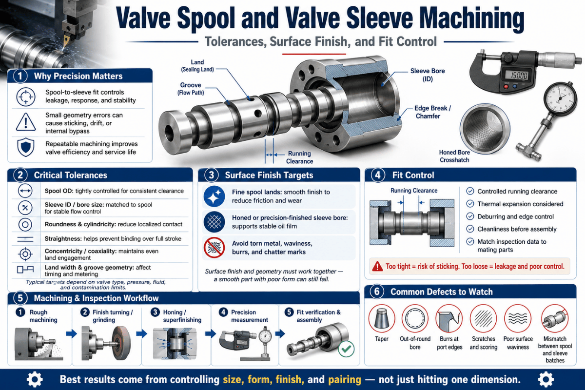
Valve spool and valve sleeve machining is where a hydraulic or pneumatic valve earns its precision. The spool slides inside the sleeve bore on a film of oil only a few microns thick, so the diameter tolerance, surface finish, and the way the pair is matched together decide whether the valve meters flow cleanly or leaks, sticks, and wears out early. This guide walks through the tolerances, surface finish, and fit control that separate a directional valve part from a servo-grade one.
| Diametral clearance (industrial directional) | 8–15 µm (≈4–7 µm radial) |
| Diametral clearance (servo / aircraft) | 0.6–2 µm |
| Surface finish (spool OD / sleeve bore) | Ra 0.05–0.2 µm after honing / lapping |
| Roundness / cylindricity | ≤1–3 µm |
| Diameter tolerance class | IT4–IT6 (OD often ±1.3 µm) |
| Fit method | Matched-pair, selective (graded) assembly |
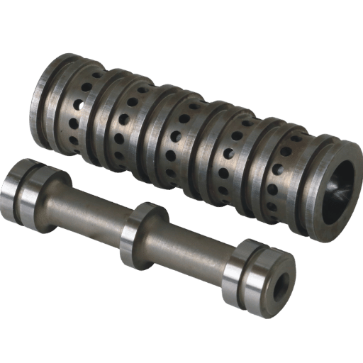
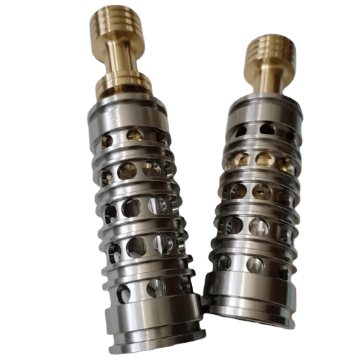
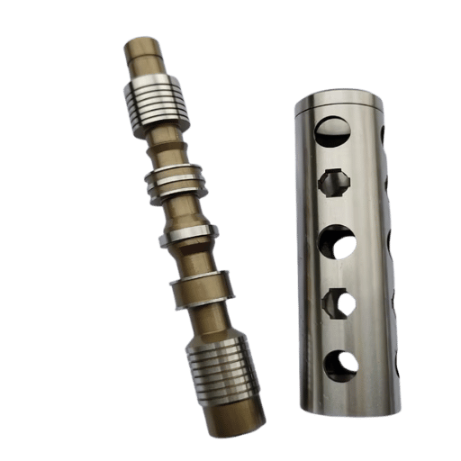
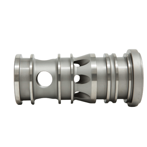
A valve spool is a precision cylindrical rod that slides inside a matched valve sleeve, or bore, to direct hydraulic or pneumatic flow between ports. Raised sections called lands block or open the ports as the spool shifts, and the sharp edges where a land meet a port form the metering edges that throttle flow. Another name for the part is a directional, slide, or spool-and-sleeve valve.
Shift the spool and it sends pressurized oil to one side of a hydraulic cylinder while connecting the other side back to tank, that’s how a single valve extends or retracts an actuator. Because the spool move on a thin oil film rather than a seal, the gap between spool and sleeve is the only thing standing between controlled flow and leakage.
Precision rises sharply with the job the valve does. A simple on/off directional valve tolerates more clearance than a proportional valve, and a servo valve, the kind that positions an aircraft flight surface, demands the tightest fit of all. Research on direct-drive electro-hydraulic servo valves published by the U.S. National Library of Medicine (PMC) shows that the spool-sleeve pair is the component most sensitive to contamination and edge wear, because the metering happens across openings well under a millimetre. That sensitivity is exactly why the machining bar is so high.
Three machined properties govern performance: the diametral clearance (fit), the surface finish (Ra), and the geometry (roundness and cylindricity). Miss any one and the other two cannot save the valve.
Valve spool and valve sleeve machining typically holds a diametral clearance of 8–15 µm on industrial directional valves, roughly 4–7 µm radial when the spool sits concentric, tightening to 0.6–2 µm for servo and aircraft valves. Forum data from working machinists puts industrial spool-to-bore clearance at 0.0002–0.0006 in, while aircraft valves are fitted down to 0.000025–0.000040 in with no drag. A modeled production spool studied by the U.S. Department of Energy’s Office of Scientific and Technical Information (OSTI) ran a radial clearance of just 1.25 µm.
| Grade | Diametral clearance | Surface finish Ra | Roundness | Final process |
|---|---|---|---|---|
| Directional | 8–15 µm | 0.2–0.4 µm | 2–3 µm | Grind + hone |
| Proportional | 4–8 µm | 0.1–0.2 µm | 1–2 µm | Hone + lap |
| Servo / aircraft | 0.6–2 µm | 0.025–0.1 µm | ≤1 µm | Lap + selective fit |
Clearance bands compiled from machinist field data and OSTI modeling; Ra and roundness from production specs (full sources at the end). Clearance is normally quoted on diameter; radial clearance is about half.
Internal leakage past a closed spool follows laminar flow through a thin annular gap, which means flow rises with roughly the cube of the radial clearance. Double the clearance and leakage climbs about eightfold. Work by NASA’s Jet Propulsion Laboratory on spool valves treats this radial leakage clearance as a deliberately controlled parameter, because spool and sleeve are machined as a matched pair. One caveat keep the rule honest: the cube law assumes a concentric, uniform gap. When the spool rests eccentric in the bore, measured leakage can rise up to about 2.5 times the concentric value, and overlap or underlap at the lands shifts it further. So a tighter mean clearance only pays off if roundness and straightness keep the gap uniform.
It’s tempting to assume the smaller the clearance, the better the valve. Field evidence overturns that. As documented research on silt lock shows, particles near the size of the clearance cause the highest stiction, about 10 µm particles produce peak static friction, while larger particles are swept aside and smaller ones pass through. A tighter gap is more vulnerable to a single tramp particle wedging the spool. There’s a second, thermal floor: non-uniform heating causes non-uniform deformation that shrinks the running clearance and can clamp the spool, especially with viscous fluid and long dwell at one position. The fit window is bounded on both sides, loose enough to move, tight enough to seal. That’s the heart of fit control.
📐 Engineering Note
For a directional spool holding 10 µm diametral clearance, target roundness and cylindricity under 2 µm per ISO geometric tolerancing practice. A common rule of thumb keeps form error below a quarter of the clearance so the gap stays uniform around the circumference.
Diameter tolerance alone doesn’t make a sealing fit; the form has to be round and straight along the whole land. In industrial production practice, spool roundness is typically held to 2 µm, straightness to 3 µm, and outside-diameter tolerance to about ±1.3 µm, with the mating bore round to roughly 3 µm and cylindrical to 5 µm. Servo-grade sleeves go tighter still, high-precision sleeve production cylindricity is commonly held within 1 µm. (The single-digit-micron figures here are representative industry production values, confirmed across machinist data and peer-reviewed measurement, not a single lab result.)
These callouts come from the geometrical product specification framework in ISO 1101, which defines roundness, cylindricity, straightness, and run-out as separate controls. The failure modes they guard against are specific: taper makes clearance vary end to end, barrel or bell-mouth shapes open the gap in the middle, and lobing leaves leak paths even when the average diameter reads correct. A spool can pass a two-point diameter check and still leak if its form is wrong, which is why roundness and cylindricity are inspected on their own instruments rather than inferred from size.
Surface finish controls three things at once: leakage, stick-slip, and wear. Functional spool and sleeve surfaces generally need Ra at or below 0.16–0.2 µm, and servo-grade parts push finer. No single process gets there from a raw turn; finish is built in stages, each tightening both roughness and form.
| Process | Typical Ra reached | What it controls |
|---|---|---|
| Precision grinding | 0.4–0.8 µm | Size + roundness baseline |
| Honing (incl. single-pass) | 0.1–0.4 µm | Bore cylindricity + crosshatch |
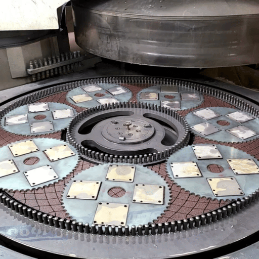
| Lapping | 0.05–0.1 µm | Final size + ultra-flat plateau |
| Superfinish / polish | ≤0.05 µm | Stick-slip + sealing land |
Honing is the workhorse for the sleeve bore, and modern single-pass honing reaches cylindricity that older process couldn’t. We run dedicated precision honing for exactly this reason. The standard that governs how these finishes are specified on a drawing is ASME B46.1-2019, which defines roughness, waviness, and lay.
“The precise fit between the sliding spool and valve body maintains the internal seal. Precision cylindricity and straightness in this bore ensures uniform clearance between the moving parts from top to bottom, allowing free movement of the spool without leakage around it.”
⚠️ Important
An Ra number alone is necessary but not sufficient. The U.S. National Institute of Standards and Technology (NIST) reports Ra alongside Rz, Rt, and RSm and publishes the measurement uncertainty for each, because two surfaces with the same Ra can behave very differently in a sealing land. Specify Rz and a measurement method, not just Ra.
The metering edge, where a spool land crosses a sleeve port, is the single feature that sets flow gain. Peer-reviewed measurement of high-precision sleeves shows these edges are never perfectly sharp: the real equivalent fillet runs 15–35 µm even on a good part, and the flow-displacement curve goes markedly nonlinear once axial displacement drops below 20 µm near closure. In other words, edge geometry decides how a servo valve behaves around null.
That’s why “sharper is always better” is the wrong mental model. Field machinists keep the metering lands sharp deliberately, not for looks but to shear and scrape trash that would otherwise pack the clearance. At the same time, a flow-force study indexed by MDPI found that conventional sharp inner-wall geometry “may not always be reasonable,” and tuning the spool wall cut destabilizing flow force. The takeaway is consistency, not extremity: the edge must be sharp and repeatable across every land, which is why the patented practice of grinding each land edge to coincide with the port control edge at null, described in U.S. Patent 5,222,521matters more than chasing a zero-radius corner.
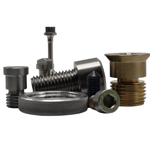
The material has to be hard enough to resist wear, stable enough to hold the micron fit after heat treatment, and friendly enough to lap. The common choices trade off differently:
| Material class | Hardness / treatment | Best for |
|---|---|---|
| 440C stainless | 55–60 HRC, through-hardened | Lapped, air-gauged servo spools |
| 9Cr18Mo stainless | 58–62 HRC | Corrosion + wear servo sleeves |
| 4140 pre-hard | 28–32 HRC, pre-hardened | Wear-resistant general spools |
| 38CrMoAlA | Gas-nitrided case ~900 HV | Hard skin + stable core |
| 15Cr carburizing steel | Case 58–64 HRC, 0.2–0.4 mm depth | High-volume directional spools |
| GCr15 bearing steel | 60–64 HRC | Dimensionally stable bores |
| 20CrMnTi | Carburized 58–62 HRC | Tough-core directional spools |
| 17-4 PH stainless | H900, ~44 HRC | Mild-corrosion service |
| Nitrided alloy steel | Surface ~65 HRC, low distortion | Long sleeves, low warp |
| TiN-coated 440C | Coating ~2000 HV, ≥10 HRC over sleeve | Anti-galling sliding lands |
Two field-proven cautions shape the choice. First, harder isn’t automatically better: pushing a carburized case toward 65–70 HRC invites edge chipping, micro-cracks, and lower fatigue life, so many shops deliberately deliver 60–64 HRC instead. Second, stainless is a trap for sliding pairs, experienced machinists warn that a close stainless-on-stainless fit tends to “wring together” and gall, and in clean hydraulic oil corrosion is rarely the real failure mode. A durable answer is surface engineering: U.S. Patent 5,222,521 (Moog) puts a thin titanium-nitride layer on the spool lands so the sliding surface runs at least 10 HRC harder than the sleeve; in test, those coated spools ran past 100 hours with no visible wear where copper-plated spools failed in 4–8 hours.
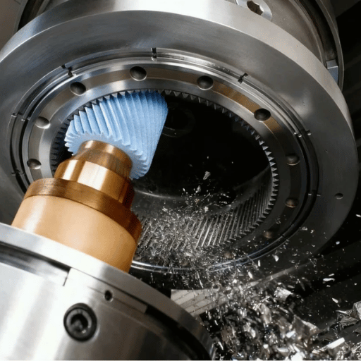
Valve spool and sleeve machining runs as a staged chain, with each step holding the tolerance the next one can’t fix: rough and finish turning establishes the form; heat treatment hardens it (and distorts it slightly); cylindrical or centerless grinding restores size and roundness; honing or lapping finishes the bore and OD to the micron band; and wire EDM cuts the throttle windows and hardened features that would burr if milled. Swiss-type turning handles the smallest spools.
A documented case from MF Engineering shows the chain in practice: a 303 stainless pilot spool and its mating bushing were pinch-turned, gun-drilled, cross-drilled, and then precision-honed to ±0.00015 in with a finish under 8 micro-inch. The bushing is matched to its body so the running fit is built, not assumed. The same matched-fit idea appears in U.S. Patent 7,007,476, which controls spool-to-sleeve diametral clearance through post-assembly surface finishing. In our own shop, this chain runs at ±0.005 mm on CNC turning, down to ±0.002 mm on wire EDM, with Swiss machining for sub-millimetre spools and honing held in-house so the fit is never shipped out and back.
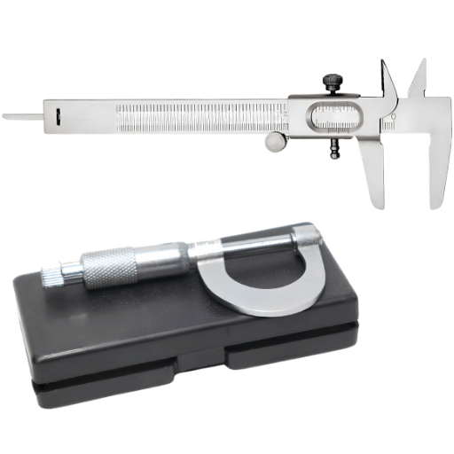
You can’t hold what you can’t measure, and at single-digit microns the gauge matters as much as the machine. Diameter and clearance are verified with air gauging, which resolves to a fraction of a micron and is fast enough for matched fitting on the shop floor. Roundness and cylindricity go on a dedicated roundness tester, not a caliper. Metering-edge geometry, the hardest feature to measure, is now checked with pneumatic methods that convert edge morphology into a flow-and-pressure index, as shown in recent peer-reviewed work using a 0.4 mm narrow-slit probe with 0.1 µm sensor resolution.
Surface finish is the trap. A reported Ra is only meaningful with its measurement conditions, because NIST surface-roughness calibration work shows the measurement uncertainty grows as the finish get finer, and a sealing surface should be judged on Rz and RSm as well as Ra. Every spool and sleeve we deliver carries first-article inspection plus CMM and in-process checks, with material certificates, so the buyer can verify the fit rather than trust it.
Holding a 5 µm clearance across a production run isn’t done by machining every spool and every bore to a single absolute size, that would demand IT3 tolerances on both parts and scrap most of them. Instead, fit is built by matching. The Match-Grade Fit Control Method works in four steps: measure each finished spool OD and each sleeve bore; sort both into narrow size grades; pair a spool to the sleeve grade that yields the target clearance; then verify the assembled clearance by air gauge or low-force slide test. This is why NASA’s Jet Propulsion Laboratory describes spool and sleeve as a machined matched pair where radial clearance is a controlled parameter, not an accident of two separate parts.
Fit control reaches past the shop, too. Because clearance-sized particles are what jam a spool, the cleanliness of the fluid the valve will run in is an acceptance variable, specified with the contamination coding of ISO 4406. A 3 µm fit in a system running dirty oil will silt-lock no matter how well it was machined. The same goes for temperature: a fit set cold can close up under viscous heating, so high-duty valves are graded with thermal margin in mind.
Most suppliers can quote a spool. Far fewer can prove they hold the fit. When you evaluate a machining partner for valve spools and sleeves, ask for evidence behind each of these:
Lecreator machines valve spools, sleeves, and bushings against this checklist with in-house honing and full first-article documentation. If you’re scoping a part, a free DFM review will flag clearance, material, and finish risks before any chips are cut.

Demand for the tightest spool and sleeve work is tracking the electro-hydraulic servo valve market, which analysts size in the low-single-digit billions and project to grow at a mid-single-digit rate, roughly 4–6% CAGR through the early 2030s, depending on the source. Electrification of mobile and off-highway hydraulics is pushing servo-grade precision into machines that used to run plain directional valves.
Two shifts will shape the next decade of machining. First, additive and hybrid manufacturing is moving into valve bodies: printed stainless hydraulic parts now hold pressures around 350 bar and let designers route internal channels without the cross-drilled leak paths of a machined block. Second, the surface-texture standard itself is evolvingASME B46.1-2019 added sections on characterizing additively manufactured surfaces and on the functional correlation of surface texture, signaling that finish specs will get more rigorous, not less. The constant underneath both is contamination control: as clearances tighten, the contamination sensitivity of the spool-sleeve pair becomes the limiting factor, and match-grading plus cleanliness specs become the real differentiators. For buyers, the action item is simple: write Rz, clearance grade, and an ISO 4406 cleanliness target into the drawing now.
This guide combines published clearance, finish, and metering-edge data from peer-reviewed and government sources (NASA JPL, OSTI, NIST, and PMC) with the clearance, honing, and matched-fit figures Lecreator holds on its own valve-component work. Where sources disagree on numbers, servo market size, for example, we give a range rather than a single figure.
Reviewed by the Lecreator Company technical team. Updated June 2026.