Supportive, Professional, Client-Focused Service
Get in touch with Lecreator Company
From prototypes to full-scale production, we’ve got you covered.


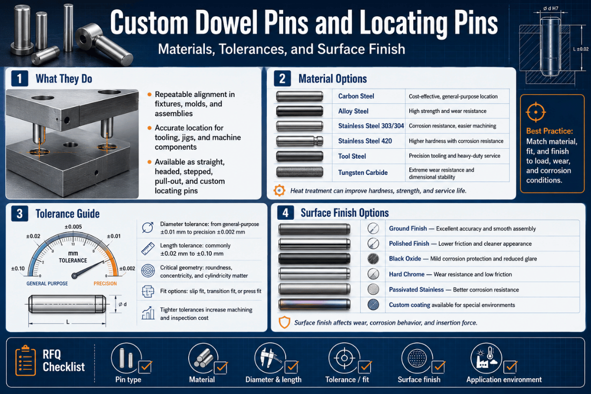
Custom dowel pins and locating pins look simple, a ground cylinder of hardened steel, yet they carry the alignment, shear load, and repeatability of a whole assembly. This guide is the engineering reference for specifying them: how to choose the material, set the press-fit or slip-fit tolerance, call out the surface finish, design the hole, and apply the round-plus-diamond locating rule that most prints get wrong.
In short: Custom dowel pins and locating pins are precision-ground cylindrical components that hold mating parts in a repeatable position. A dowel pin carries shear load and sets location between two parts; a locating pin positions a workpiece on a fixture. Both are defined by four specs, material, fit class (press or slip), dimensional tolerance, and surface finish, plus the hole they seat into.
| Diameter range | 1/16″–1″ standard; 1–20 mm metric; custom beyond on request |
| Standard tolerance | Inch +0.0002″ oversize (press); metric m6/h7 (ASME B18.8.2 / ISO 8734) |
| Materials | Alloy steel, 303/304/316/416 and 17-4 PH stainless steel, A2/O1 tool steel, brass |
| Hardness | Up to 60+ HRC (through- or case-hardened); core 47–58 HRC for standard hardened pins |
| Surface finish | 32 µin (0.8 µm) Ra typical (ground); to 8 µin (0.2 µm) for precision; lapped finer still |
| Standards | ASME B18.8.2-2020, ISO 2338, ISO 8734, DIN 6325/DIN 7, NAAMS (automotive) |
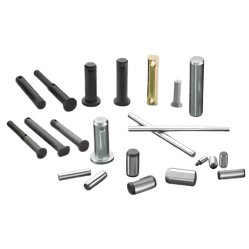
Dowel pins join and align two parts that bolt together, carrying the shear load and fixing their relative position per standard machine-design practice; a locating pin hold a workpiece in a known position on a fixture so each part is machined or assembled the same way. Both are headless, ground cylindrical fasteners, and both come standard off the shelf, so the practical question is when a custom pin earns its cost.
The honest answer: most assemblies run fine on standard pins. Custom dowel pins and locating pins pay off when you need a non-standard diameter or length, an exotic or higher-hardness material, a special end form, or an oversize for a worn hole. Field practitioners on engineering forums make the division simple, dowels carry shear and set repeatable location, while bolts only clamp, which is why a good design uses both rather than asking screws to locate.
There’s one trap worth flagging up front, because it drives half the custom requests we see: two identical round dowels don’t reliably locate a part. Under real tolerance and thermal growth, two round pins fight each other and the part can refuse to drop on. We call this the Over-Constraint Tax, and the fix, one round pin and one diamond pin, is covered in the locating-pin section below.
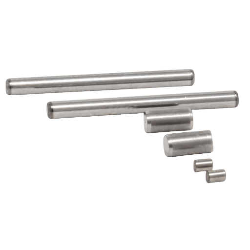
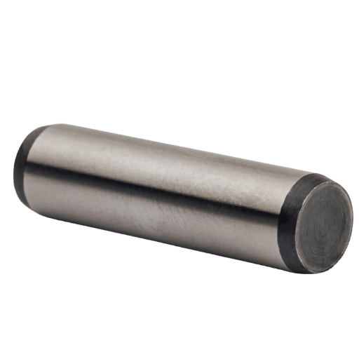
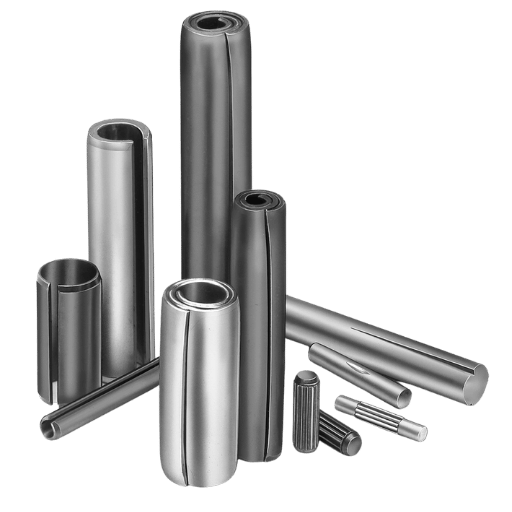
Dowel pins are solid, precision-ground cylinders that press- or slip-fit into a reamed hole for exact location. Spring (roll) pins are hollow and compressible, so they forgive a rough drilled hole but locate loosely. Taper pins are conical and seat by wedging into a reamed taper, holding well but harder to set precisely. For accurate, repeatable alignment in a machined assembly, the dowel pin is the right tool; the spring pin trades precision for tolerance of a sloppy hole.
Material is the first specification that actually change how a pin behaves, because it sets hardness, corrosion resistance, and machinability at the same time. The default is hardened alloy steel; you move to stainless steel for corrosion, to 17-4 PH or tool steel for hardness with some corrosion resistance, and to brass when you need non-magnetic or non-sparking parts. The table below is a decision aid, the Pin Material Duty Index, mapping each common material to its heat-treated hardness, corrosion behavior, and the duty it suits.
| Material | Hardness (heat-treated) | Corrosion resistance | Best duty |
|---|---|---|---|
| Alloy steel (e.g. 4140-class, standard hardened dowel) | Core ~47–58 HRC, case 60 HRC min | Low (needs coating) | General load-bearing dowels, shear pins |
| 12L14 free-machining steel | Soft (~70–90 HRB) | Low | Low-cost custom locating pins, light duty |
| 303 stainless steel (300 series) | Soft (<~25 HRC, not hardenable) | Good | Easy-machining alignment pins, light load |
| 316 stainless steel | Soft (<~25 HRC) | Excellent (marine/chemical) | Corrosive environments, low wear |
| 416 stainless steel (400 series) | ~36–42 HRC (hardened & tempered) | Moderate | Hardenable stainless dowels, repeated press-fit |
| 17-4 PH stainless steel | H900 ≈44 HRC (down to ≈33 HRC at H1150); ~1310 MPa UTS | Very good | Aerospace/medical pins needing strength + corrosion |
| A2 / O1 tool steel | 58–62 HRC | Low | High-wear locating pins, die and mold work |
| Brass | Soft | Good | Non-magnetic, non-sparking, electrical assemblies |
The practical mistake here’s reaching for 303 or 316 stainless steel for a press-fit pin because it’s “stainless.” Both are austenitic and stay below roughly 25 HRC, so a repeated press-fit galls and the pin wears. When you need stainless plus hardness, 416 or 17-4 PH is the right call; when you need maximum wear life, tool steel beats stainless. We carry these distinctions into our own material selection for machined parts, because the alloy also drive cost and lead time.
Standard dowel pins are hardened alloy steel, ground after heat treatment for a core of about 47–58 HRC. For corrosion resistance, 303 and 316 stainless steel cover light-load alignment, while 416 and 17-4 PH stainless steel give hardness for press-fit duty. Tool steels such as A2 and O1 reach 58–62 HRC for high-wear locating pins, and brass serves non-magnetic or non-sparking assemblies. Pick the material from load, environment, and wear, not from habit.
Fit is the difference between a pin that locates and a pin that falls out, or one you cannot install. Under standard machine-design fit practice, a precision dowel pin is ground slightly oversize and pressed into a reamed hole, so the interference, not the pin alone, sets retention. Under ASME B18.8.2, a standard hardened dowel pin is ground about +0.0002″ over its basic diameter and pressed into a hole reamed to nominal, so that small interference, not the pin alone, provides retention. A slip fit comes from reaming the hole a few tenths larger rather than from changing the pin, and oversize-series pins add about +0.0010″ for reworked holes. Metric pins follow ISO 8734 and DIN 6325 with m6 (interference) or h7 (clearance) tolerances on diameters from 1 to 20 mm. Confirm exact diameter limits against the current ASME edition.
The interference itself is small and predictable. A standard inch dowel is made about 0.0002″ over its nominal diameter and seats into a reamed hole at that nominal size; special oversize pins add roughly 0.0010″ for a worn or reworked hole. The Press-Fit Interference Window below consolidates the bands engineers reach for most often.
| Nominal diameter | Pin tolerance (press) | Reamed hole target | Fit / use |
|---|---|---|---|
| 1/16″ (1.59 mm) | +0.0002″ oversize | Nominal, dowel reamer | Light press, small assemblies |
| 1/8″ (3.18 mm) | +0.0002″ oversize | Nominal, dowel reamer | General press-fit location |
| 1/4″ (6.35 mm) | +0.0002″ oversize | ~0.0002″ under pin | Standard machine dowel |
| 3/8″ (9.53 mm) | +0.0002″ oversize | ~0.0002″ under pin | Heavier shear duty |
| 1/2″ (12.7 mm) | +0.0002″ oversize | ~0.0002″ under pin | Structural / tooling |
| Oversize (any inch dia) | ~+0.0010″ | Re-ream worn hole | Rework / repair fit |
| 6 mm (m6) | +0.012/+0.004 mm | H7 reamed | Metric press-fit (ISO 8734) |
| 10 mm (m6) | +0.015/+0.006 mm | H7 reamed | Metric press-fit |
| Slip-fit (inch) | Pin at/under nominal | Reamed +0.0003″ over | Removable alignment, dowel changed often |
Source: ASME B18.8.2-2020 dimensional classes; metric m6 bands per ISO 8734. Confirm exact limits against the current standard for your diameter.
Common shop practice sets the engaged hole depth at two to three times the pin diameter, for a 6 mm pin, about 12 to 18 mm, which gives enough bearing length to resist tipping without wasting material. Drive the fit through the hole, not the pin: ream the hole to the nominal size and let the standard 0.0002″ pin oversize create the press.
For a slip-fit, ream a few tenths larger so the pin slides yet still locates. Going deeper than three diameters rarely adds strength and complicates removal.
Holding these limits is its own discipline; see our guide to tight-tolerance machining for how a reamed dowel hole is produced and gauged in practice.
Surface finish governs how a press-fit pin seats and how long a locating pin survives. Precision dowel pins are centerless-ground to a typical 32 µin (0.8 µm) Ra; precision and aerospace work specifies finer, commonly 8–16 µin (0.2–0.4 µm) Ra, with lapped pins smoother still. These Ra figures are industry-typical for ground and lapped pins, and are defined and measured per the surface-texture standard ASME B46.1-2019; specific aerospace pin standards set their own finish limits, so confirm against the controlling spec. Smoother pins press in with less galling and hold their retention force more repeatably, which matters when the same hole is used across a production run.
Hardness sets wear and shear. Standard hardened dowel pins are heat-treated to a core of roughly 47–58 HRC with a case of 60 HRC minimum, giving a single-shear strength on the order of 130,000 psi (about 896 MPa) for hardened alloy pins that lets a small pin carry real load, confirm the exact grade and ASME B18.8.2 edition for a load-bearing design. Locating pins that index thousands of parts are often tool steel at 58–62 HRC, and a thin black-oxide or phosphate coating adds mild corrosion resistance without changing the fit.
Call out finish and hardness together with the fit. A useful baseline on a custom dowel drawing: 32 µin (0.8 µm) Ra ground surface, 50–55 HRC for alloy steel, and the diameter toleranced to the press class (+0.0002″ oversize). For high-cycle locating pins, raise hardness to tool-steel range and tighten finish to 8–16 µin (0.2–0.4 µm) Ra. Hardened pins beyond about 50 HRC are ground or wire-cut rather than turned, see our note on wire EDM for hardened materials.
The hole, not the pin, decides whether a press-fit work, because the pin is bought to a known size and the hole is what you control. Use a dowel-size reamer rather than a nominal drill: experienced machinists keep both a tight and a loose reamer for each pin size, roughly −0.0005″ on the tight side for a firm press and +0.0005″ on the loose side for a slip, and select by the fit they need. A drilled-only hole run oversize and bell-mouthed, so the pin neither presses nor locates.
Blind holes carry a failure mode that catches teams off guard. When you press a pin into a closed reamed hole, the trapped air, and any oil, has nowhere to escape, so it compresses and hydraulically resists the pin: you can’t seat it to a repeatable depth, the back-pressure can push it part-way out again, and in a tight interference fit that trapped pressure can damage the surrounding boss. Tool-and-die makers have flagged this for decades; as one engineering discussion on venting puts it, you can’t bottom a pin out in a blind hole unless it is vented, because that last bit of travel builds up almost unlimited pressure. The fix is routine once known: vent the blind hole with a small cross-drill, grind a flat or relief channel on the pin to the depth of the press, or specify a pull-type (threaded) or flat-vented dowel that lets trapped fluid escape and gives a way to extract the pin later. Producing those clean, straight bores is a precision drilling and reaming task in its own right.
Plan removal at design time. Press-fit pins aren’t meant to come out often; when a part must be serviced, use a slip-fit pin, a pull dowel with an internal thread, or a through hole you can drive the pin out from the back.
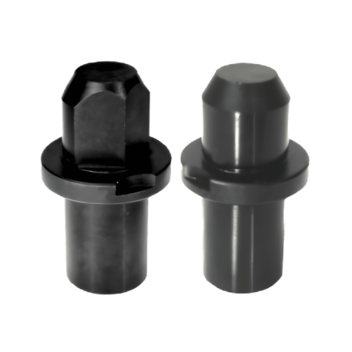
Locating pins come in more forms than dowels because their job is to position a workpiece, not just join two plates. The common types are round (plain or shouldered), bullet-nose and conical for easy loading, diamond (relieved) for radial location, floating to absorb hole-spacing error, and expanding for locating on a bore. Each is press-fit into the fixture body or mounted in a renewable liner for long production runs. A USPTO patent on fixturing hardware catalogs the same family, clamping, quick-release, drift, and indexing pins, confirming how standardized this taxonomy is.
The principle that ties them together is how many degrees of freedom each pin removes. This is where the Over-Constraint Tax becomes concrete. A round pin in a hole is a four-way locator: it fixes the part in two directions (the X and Y of that hole). Add a second round pin and you try to fix four directions with two holes whose center distance can never be perfect, so the part binds and may not load at all. The standard fix, taught in every jig-and-fixture course under the 3-2-1 locating principle, is to make the second pin a diamond.
“The first thing I check on a two-pin print is whether the second pin is a diamond. Two round dowels look right on the drawing and then fight you on the bench, the parts will not seat, and people blame the machinist instead of the redundant location.”
A round pin is a four-way locator: seated in a hole, it stops the part from moving along two axes. A diamond (relieved) pin is a two-way locator: its flats touch the hole on only two sides, so it stops rotation about the round pin while letting the part slide slightly between the holes. Pairing one round (4-way) with one diamond (2-way) locates the part fully without over-constraining it.
These geometries scale into automotive and aerospace fixtures, where families like NAAMS standardize round and diamond locating pins; the same logic underlies our automotive CNC fixture components.
Calling the right standard on a print prevents most sourcing confusion, because each standard fixes the diameter classes, tolerances, and pull-out features. Inch dowels follow ASME B18.8.2-2020; metric parallel pins follow ISO 2338 (unhardened) and ISO 8734 (hardened), with DIN 6325 the common hardened-ground equivalent. Note that the ISO pin standards remain at their 1997 editions, current and in force, but cite the year so a buyer pulls the right document.
| Standard | Covers | Typical fit |
|---|---|---|
| ISO 8734 (1997) | Hardened steel + martensitic stainless parallel pins (metric) | m6 press |
| ISO 2338 (1997) | Unhardened parallel pins (metric) | m6 / h8 |
| ASME B18.8.2-2020 | Hardened ground machine dowel pins (inch) | +0.0002″ oversize press |
| DIN 6325 / DIN 7 | Hardened ground / unhardened parallel pins (metric) | m6 / h8 |
| NAAMS | Round and diamond locating pins (automotive fixtures) | Fixture press |
Custom dowel pins and locating pins are worth ordering when a standard pin can’t meet the diameter, length, material, hardness, or end form your assembly needs. Trade press shows where this is routine, modular fixturing systems built on grids of precisely spaced dowel holes, for example, depend on pins matched to the plate. The decision is simple: if a catalog pin fit, buy it; if any one of diameter, length, alloy, hardness, or feature falls outside stock, specify a custom pin.
At Lecreator we machine custom dowel and locating pins by CNC turning and cylindrical grinding, hold tolerances to within about ±0.005 mm, harden to 60+ HRC, and grind finishes toward 0.2 µm Ra, with material certs available under our ISO 9001:2015, IATF 16949, AS9100D, and ISO 13485 systems. For buyers comparing offshore sourcing, the landed cost and lead time are part of the spec, which is why custom pins are quoted alongside the rest of our precision CNC machining service.
Have a print with non-standard pins, tight tolerances, or hardened material?

Two shifts are worth watching if you specify pins in 2026. First, CNC automation and in-process gauging now make ±0.005 mm pin tolerances routine rather than premium, so designers can ask for tighter fits with confidence. Second, material demand is tilting toward 17-4 PH and tool steel as more pins move into aerospace, medical, and high-cycle fixtures, the same pull we see in rising interest for hardened pins.
Market analysts put steady growth behind this: independent market-research firms estimate the dowel pin market at roughly $3.8 billion in 2025, growing near a 5% compound annual rate through the next decade. If you’re planning a 2026 program, the practical move is to lock material and tolerance on the print now, including the 2020 ASME B18.8.2 edition, and qualify a manufacturer who can hold the finish, not just the diameter. (Updated June 2026.)
Lecreator machines custom dowel pins and locating pins by CNC turning and cylindrical grinding, so the tolerances, fits, and finishes above reflect what we hold on real parts, press classes per ASME B18.8.2, hardness to 60+ HRC, and ground finishes toward 0.2 µm Ra. Where a number come from a standard or third-party data, we cite it; where it depends on your geometry, we say so. Reviewed by the Lecreator technical team.