Supportive, Professional, Client-Focused Service
Get in touch with Lecreator Company
From prototypes to full-scale production, we’ve got you covered.


| Common body materials | 6061-T6 aluminum, ductile iron 65-45-12, 4140 steel, 316 stainless |
| Typical working pressure | ~3,000 psi (210 bar) for 6061 aluminum; ~5,000 psi (350 bar) for ductile iron |
| Valve interface standards | ISO 4401 / NFPA D03–D08 / CETOP 3–10; SAE J1926 (ISO 6149) O-ring boss ports |
| Critical accuracy points | Cross-bore intersection position, cartridge cavity concentricity, valve-pad flatness, seal-face finish |
| Target fluid cleanliness | ISO 4406 18/16/13 (general) to 16/14/11 (servo/proportional) after flushing |
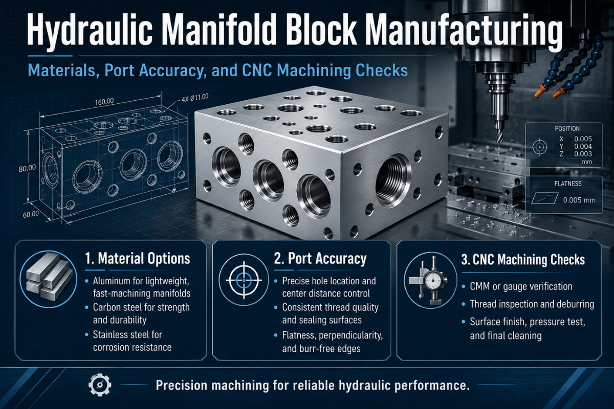
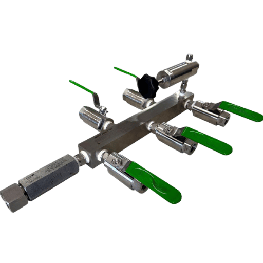
Strip away the marketing and a manifold is a solid block of aluminum or iron with holes drilled through it. Some holes are ports where hoses or valves connect; others are internal passages that link those ports into a working hydraulic circuit. Mount the valves directly to the block and you’ve replaced a tangle of tees, fittings, and hose with one machined part. Engineers call that integration a hydraulic integrated circuit (HIC).
So why choose a part that’s genuinely hard to make over components you can simply plumb together? Three reasons that hold up in the field: fewer external joints means fewer places to leak; a compact block survives vibration that loosens threaded connections; and consolidating valves onto one mounting surface make a machine easier to service. Industry sources commonly cite a 60–80% footprint reduction and a drop from 20–30 external connection points to as few as 2–4 when a multi-valve circuit moves onto a manifold. The catch is that every leak path you removed from the outside now live inside the block, where you can’t see it, which is exactly why manufacturing quality, not the concept, decides reliability.
“The cavity looks like a mildly conical shape with cylindrical steps, and at each step is a cross drilling corresponding to each valve port.”
Before a shop quotes a block, it needs to know which construction you want, because each one machines differently.
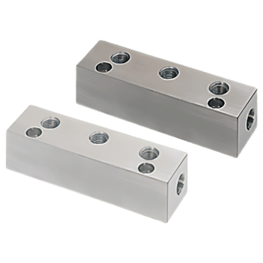
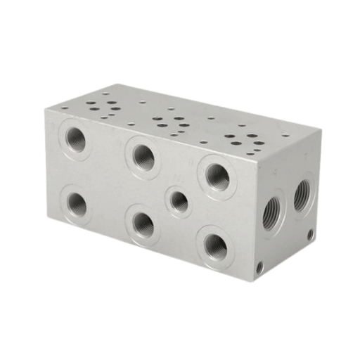
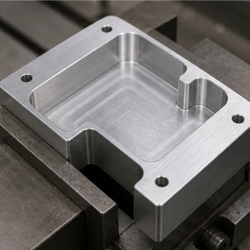
A single billet with every passage and cavity drilled into it. This is the densest, most leak-free option and the hardest to machine, because all the internal routing is bespoke. Monoblock designs handle the highest pressures and the tightest packaging.
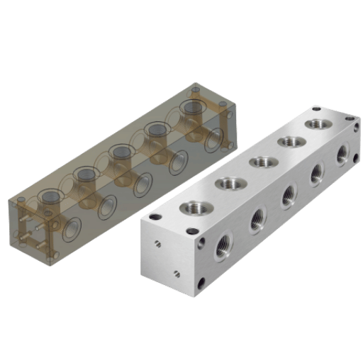
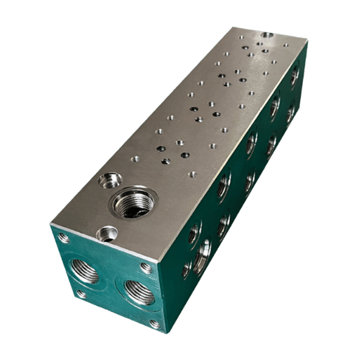
Machined bar stock that accepts standard subplate-mounted valves bolted in a stack, with sandwich (modular) cetop valves adding pressure or flow functions between plates. Bar manifolds run from D03 up to D10 sizes and are far more economical than custom blocks because the valve interfaces and mounting holes are standardized. As Fluid Power World notes, most of the drilling is perpendicular to the surface, the only real challenge is the diagonal porting to each valve interface.
Valve functions are built into machined cavities inside the block. Screw-in cartridge valves handle directional, pressure, and flow control; large slip-in cartridges, also called logic elements, pass flow in the thousands of gallons per minute. Cartridge blocks give a designer near-infinite control combinations from a catalog of standard valve products, but the cavities are the most demanding feature on the whole part.
| Type | External leak points | Serviceability | Best use |
|---|---|---|---|
| Monoblock | Lowest (2–4) | Replace whole block | High pressure, tight packaging |
| Sandwich / modular bar | Medium | Swap one valve in the stack | Standard industrial circuits |
| Cartridge / HIC | Low | Unscrew a cartridge in under a minute | Compact, complex logic |
Here is the result that surprises buyers who expect a long material menu: in production, almost every hydraulic manifold is one of two materials, and the working pressure picks which. One caveat first, under NFPA T3.5.1, a manifold’s maximum working pressure is set by the manufacturer for the specific design and test method, not by the metal alone, and ISO 10771-1 frames fatigue testing around the part’s pressure-containing envelope. The figures below are the ratings manufacturers publish for standard manifold grades, so treat them as calibrated examples, not material laws. With that said: manufacturers rate standard aluminum 6061-T6 (ASTM B221) manifolds around 3,000 psi (210 bar) working with a proof rating near 6,000 psi, while ductile iron 65-45-12 (ASTM A536) roughly doubles that to about 5,000 psi (350 bar) working, with proof and burst ratings near 10,000 and 20,000 psi. Everything else on the chart is the exception you reach for when corrosion, weight, or extreme pressure forces your hand.
| Material | Typical working pressure | Why you pick it | Machining note |
|---|---|---|---|
| 6061-T6 aluminum | ~3,000 psi (210 bar) | Light, low cost, anodizes; default for mobile | Easiest to machine; fast drilling |
| 7075-T6 aluminum | Higher strength, similar fluid limit | Strength-critical, weight-sensitive aerospace | Less corrosion-tolerant; not for welding |
| Ductile iron 65-45-12 | ~5,000 psi (350 bar) | Higher pressure, vibration damping | Tougher cut; needs coating for corrosion |
| High-grade ductile (e.g., Dura-Bar) | Up to ~6,500 psi (NFPA T2.6.1) | Mobile high-pressure circuits | Consistent grain, drillable |
| 4140 alloy steel | Above ~5,000 psi (varies) | Very high pressure, high strength | Hard to drill long passages; slower |
| 17-4 PH stainless | High (strength + corrosion) | Strength plus corrosion resistance | Work-hardens; controlled feeds |
| 316 stainless | Moderate (corrosion-led) | Marine, subsea, food, chemical | Gummy; sharp tools, flood coolant |
| Brass C360 | Low | Instrumentation, low-pressure pilot | Free-cutting; excellent finish |
| 5052 / 2024 aluminum | Lower (situational) | Formed plates, niche aerospace | Rare for monoblock manifolds |
Ratings reflect standard manifold grades (ASTM A536 ductile iron, ASTM B221 6061 aluminum, NFPA T2.6.1 high-strength ductile). Treat them as a starting point and confirm the rated pressure for your exact part geometry and wall thickness.
One field note from our own shop: the highest-strength aluminum isn’t always about pressure. On a battery-cooling manifold program we run in 7075-T6 at 2,500 units a month, the alloy was chosen for stiffness and dimensional stability at thin walls, holding ±0.001 in (0.025 mm) concentricity at a process capability above Cpk 1.67, strength bought us repeatability, not a higher fluid rating. If your manifold is aluminum and you want the surface and corrosion story, see our notes on aluminum CNC machining; for corrosion-led blocks, stainless steel machining covers grade trade-offs.
Port accuracy starts at the valve interface. If a block is going to accept off-the-shelf directional valves, the mounting pattern has to match an international standard so the bolt circle, the porting, and the locating pin land where the valve expects them. The three names you will seeISO 4401, NFPA T3.5.1 (the “D” codes), and CETOP, describe the same interfaces under different bodies. A D05 pad is an ISO 4401-05 pad is a CETOP 5 pad.
| NFPA (T3.5.1) | ISO 4401 | CETOP | Approx. nominal flow* |
|---|---|---|---|
| D02 | ISO 4401-02 | CETOP 2 | ~ up to 15 L/min |
| D03 | ISO 4401-03 | CETOP 3 | ~ up to 40 L/min |
| D05 | ISO 4401-05 | CETOP 5 | ~ up to 80 L/min |
| D05H | ISO 4401-05 (high) | CETOP 5H | ~ up to 120 L/min |
| D07 | ISO 4401-07 | CETOP 7 | ~ up to 300 L/min |
| D08 | ISO 4401-08 | CETOP 8 | ~ up to 600 L/min |
| D10 | ISO 4401-10 | CETOP 10 | Largest standard pad |
*Nominal flow bands are approximate and vary by valve series and pressure drop; confirm against the specific valve datasheet. Crosswalk equivalence (ISO 4401-05 = CETOP 5 = NFPA D05) is the fixed part.
📐 Engineering Note
An interface seals only if the valve-pad face is flat and the bolt pattern is in position. A symmetrical D03 pad has a diamond port layout that will bolt up rotated 180° and run backwards, so the locating-pin hole has to be in true position, not just close. For ports on the block, a straight-thread O-ring boss (SAE J1926 / ISO 6149) seals on a controlled face and is widely preferred over an NPTF tapered thread, which seals on deforming threads and is harder to seal repeatably at high pressure. Thread geometry matters more than most drawings show, see our guide to thread design for CNC machined parts.
This is where a manifold is won or lost. The internal circuit is built by drilling passages that intersect, one bore crosses another so fluid can turn a corner inside solid metal. On a large block that can mean drilling a deep bore from each end and meeting in the middle; machinists on r/Machinists describe drilling a 2-inch cross-bore “from either end and planning and hoping to meet in the middle,” which is exactly as nerve-wracking as it sounds. Deep, accurate passages are a job for gun drilling or deep hole drilling, not a stub drill in a chuck.
Every place two bores meet, the drill breaks through into open space and throws up a burr on the far wall. That intersection burr is the single most under-discussed failure mode in manifold manufacturing, and the one competitor guides skip entirely.
A finished manifold can pass every dimensional check and still destroy the system it feed, because intersection burrs fail downstream: a burr left at a cross-bore breaks loose under flow, becomes a hard particle in the oil, and lodges in the spool of the very valve the manifold supplies. The block measure perfect on the CMM; the pump and valves die three weeks later. This matters because particle contamination is the dominant hydraulic failure mechanism, SAE technical work attributes roughly 70% of hydraulic-system failures to oil particle contamination, and a cross-bore burr is one of the few contamination sources a machine shop fully controls. Deburring specialists call burrs “a hidden but critical risk” formed during drilling. That’s why deburring and cleanliness, covered below, are acceptance criteria, not housekeeping.
Passages are drilled in a planned sequence so that bores intersect at controlled positions and depths, with plugs (threaded or ball) sealing the drill-entry holes that aren’t ports. Cartridge cavities are machined separately, with stepped reamers or form tools cutting the conical, multi-diameter cavity in as few as two operations.
Concentricity between the cavity steps must be held so the cartridge seats and seals. Hard accuracy targets are the true position where bores intersect, the depth of each cavity step, and the flatness and finish of every sealing face, miss the intersection and you get no flow or a blowout; miss the cavity and the cartridge leaks internally.
A typical manifold run through a fixed sequence: square the stock, machine the valve pads, drill the ports and intersecting passages, ream the cavities, tap the threads, deburr, wash, and inspect. Each time the part comes off the machine and go back on is a new setup, and every setup adds a little tolerance stack-up between the features cut in different orientations. That’s why the number of setups drives the achievable true position across faces.
Three-axis milling needs multiple setups to reach every face of a manifold; a 5-axis machine can reach several faces in one fixturing, which is why a sophisticated shop can finish a manifold “in two operations or less” where a 3-axis shop needs five. Fewer setups means tighter feature-to-feature position, the same logic behind tight-tolerance machining on any precision part. Cutting itself is ordinary milling and drilling; see CNC milling for the envelope.
Then comes deburring, which on a manifold isn’t a finishing afterthought, it’s the job. Machinists on Practical Machinist describe deburring hole intersections as “manual and time-consuming,” and for good reason: the burr sit at the bottom of a crossing bore where no tool reaches easily. The common methods, from least to most controlled:
Whichever method a shop uses, the bore intersections still have to be honed and inspected; for cylindrical bores that need a controlled finish, honing brings the surface into the right range. Designing the internal corners to be reachable in the first place save all of this.
Because the Cross-Bore Burr Trap means a manifold can measure correct and still fail, acceptance has to test function, not just dimensions. The checks below are the ones a buyer should require on a custom block, and the ones that separate a real fluid power shop from a job shop that happens to own a mill.
This is where in-process measurement earns its keep. On an aerospace hydraulic actuator-housing program, we hold a critical bore to ±0.0005 in (0.013 mm) using high-pressure coolant and Renishaw in-process probing that verifies dimensions at three stages and auto-corrects offsets before the part ever reaches final inspection, so a drifting tool is caught on the machine, not on the CMM after the cut is scrap. Catching the error early is the difference between a 100% yield run and a rejection rate that eats the program.
If you’re buying a custom manifold, the quality you get back is largely set by the package you send. A few design-for-manufacturing rules keep a block machinable and right the first time:
What a shop needs to quote and build accurately: a 3D model (STEP), a 2D drawing with the port schedule and tolerances, the working and proof pressure, the fluid and material, the target ISO 4406 cleanliness, and any test or certification requirements. For overseas sourcing, a quote on a Delivered Duty Paid (DDP) basis folds shipping and the Section 301 tariff into one landed number so the comparison is honest. A manifold can be a prototype first and a production part later; a rapid-prototyping run proves the circuit before you commit tooling, and the broader CNC machining service covers the move to volume.
Buyers now ask one thing more than anything else: should the next manifold be machined or metal 3D printed? The honest answer isn’t the one the hype imply. Additive manufacturing lets a designer route curved, conformal channels that no drill can follow, which cuts pressure drop and weight, lifts flow performance, and removes the drilled-and-plugged cross-bores entirely. The gains in peer-reviewed redesigns aren’t marginal: one design-for-additive study cut a 316 stainless manifold from 16.2 kg to 1.4 kg, and an optimized laser-melted (SLM) manifold reduced weight by 84%, volume by 44%, and principal-path pressure loss by more than 40%. That’s why aerospace and motorsport teams redesign weight-critical manifolds with additive.
But additive doesn’t replace machining, it depends on it. As Additive Manufacturing Media documents, printed parts still go to a mill for their sealing faces, ports, and cavities, because as-built internal surfaces are too rough and dimensions too loose to seal a hydraulic interface. Patents for additive manifolds, such as conformal-cooling designs in EP4091238A4 and the hybrid heat spreader in US12029008B2describe exactly this hybrid path: print the complex channels, then machine the features that have to seal.
✔ When additive wins
⚠ When CNC still wins
The CNC-vs-Additive Manifold Decision Line: if your manifold needs conformal channels or shaves grams on a flying part in low volume, print it, then machine the faces. If it’s a production block judged on pressure, cost, and a clean internal finish, machine it. Most manifolds sold today still fall on the machined side of that line; additive is a growing exception, not a replacement. The cost trade is worth running both ways, our comparison of CNC machining vs 3D printing and our 3D printing service lay out where each pays off. The hydraulic manifold market is forecast to grow at roughly a 3–6% annual rate through the early 2030s across published analyst estimates, so this decision will only get more common.
Have a manifold design, or just a hydraulic schematic, and need it machined to spec? Send the STEP file and port schedule for a DFM review and a DDP quote.
Yes, metal additive manufacturing is now used for hydraulic manifolds that need conformal internal channels, for weight-critical aerospace and motorsport parts, and for low-volume designs, with peer-reviewed redesigns reporting weight cuts above 80 percent, volume cuts near 44 percent, and pressure-loss reductions of more than 40 percent versus the machined original.
But printed manifolds are almost always finished on a mill, because as-built internal surfaces are too rough and dimensions too loose to seal hydraulic interfaces. The economics also flip with quantity and pressure: below a few units, printing avoids setup and tooling, yet as volume rises the per-part cost of machining wins, and high-pressure or fatigue-critical blocks still favour a machined body. For most production work, CNC machining still dominates, and many printed manifolds are a hybrid of both processes.
We machine hydraulic manifolds and valve blocks in aluminum, ductile iron, and stainless on the same floor as our actuator and cooling-manifold programs, so the tolerances, deburring methods, and Renishaw in-process checks described here are the ones we run in production, not generic advice. Material ratings are stated against their governing ASTM and NFPA grades; verify the rated pressure for your exact geometry before you commit. Reviewed by the Le Creator Technology Co., Ltd. technical team.