Supportive, Professional, Client-Focused Service
Get in touch with Lecreator Company
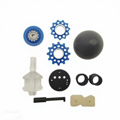
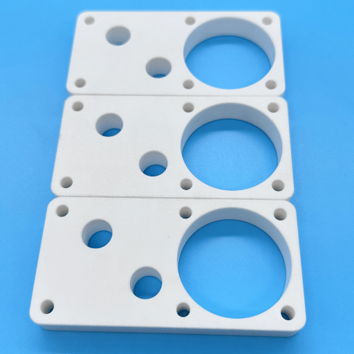
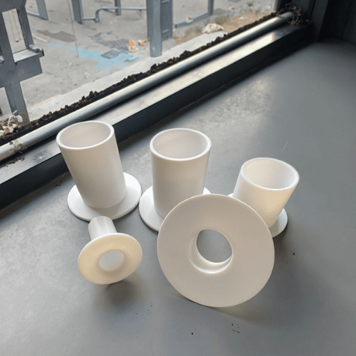
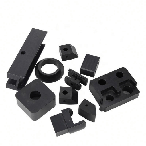
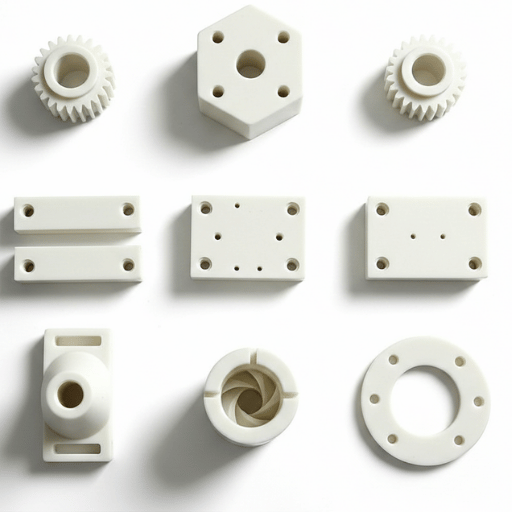
From prototypes to full-scale production, we’ve got you covered.


A Practical Guide to Machining PTFE: From Tool Selection to Final Tolerance
| Full Chemical Name | Polytetrafluoroethylene (PTFE) — DuPont trade name: Teflon |
| Density | 2.13–2.19 g/cm³ |
| Melting Point | 327 °C (621 °F) |
| Max Continuous Service Temp | 260 °C (500 °F) |
| Coefficient of Friction | 0.05–0.10 (lowest of any solid polymer) |
| Coefficient of Thermal Expansion | 100–200 × 10⁻⁶/°C (roughly 10× higher than steel) |
| Achievable Machining Tolerance | ±0.025 mm (±0.001 in) with annealing; ±0.13 mm (±0.005 in) without |
| Common Machining Processes | CNC turning, CNC milling, drilling, sawing |
PTFE occupies a class by itself. The compound that coats non-stick surfaces and provides the sealing for chemical reactors does not behave like any other plastic once introduced to a cutting tool. Its coefficient of thermal expansion is approximately an order of magnitude higher than steel’s. It creeps under sustained load, and it undergoes a crystalline phase change near room temperature capable of shifting its dimensions by several percentage points in a narrow 3 °F window.
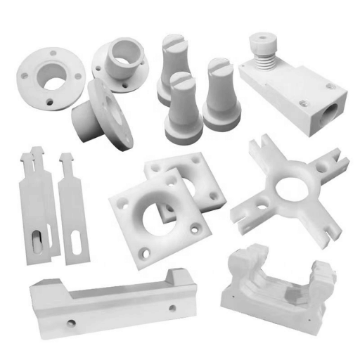
None of these properties are an insurmountable barrier to machining the material—products like valves, bushing, seals, and custom knobs are produced in PTFE daily. However, the standard plastics approach will generate a significant amount of scrap. This guide covers the tooling, feed rates, annealing cycles, and metrology necessary to produce tight-tolerance parts from a material that resists dimensional stability at every phase.
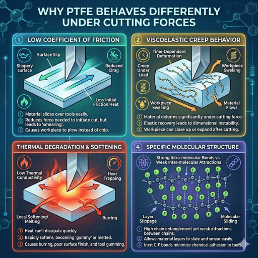
Polytetrafluoroethylene (PTFE) is a semi crystalline fluoropolymer with a fully fluorinated backbone “back-boned” on carbon. The chemistry bestows PTFE with an extremely low coefficient of friction (0.05-0.10, per the DuPont Teflon PTFE Properties Handbook), chemical resistance, and stable performance at high temperatures up to 260 °C. These unique properties also create three characteristics that directly influence any machining operation:
First, thermal expansion. According to data compiled by Professional Plastics, PTFE’s coefficient falls between 100 and 200 × 10⁻⁶/°C — roughly 10 times that of carbon steel. A PTFE component machined at 22 °C will grow measurably if the shop warms to 28 °C by afternoon.
Second, there is a crystalline transition near 19–20 °C (about 66–68 °F). NIST thermal expansion research documents a first-order crystalline transition in this narrow temperature band, producing a disproportionate dimensional jump. In practice, parts within tolerance during evening shifts frequently measure out of spec by morning as shop temperatures cross this threshold.
📐 Engineering Note: Thermal Expansion Comparison
| Material | CTE (× 10⁻⁶/°C) | Relative to PTFE |
|---|---|---|
| PTFE (virgin) | 100–200 | Baseline |
| PEEK | 47–54 | ~0.4× |
| Delrin (Acetal) | 85–110 | ~0.7× |
| Aluminum 6061 | 23.6 | ~0.2× |
| Carbon Steel | 10–12 | ~0.08× |
Sources: Professional Plastics thermal properties database; NIST measurement data
Third, cold flow. PTFE deflects permanently under sustained mechanical stress — a property called creep. Clamping a PTFE blank too tightly does not spring back the way a metal would. The material yields, and the part goes out of tolerance the moment you release it. Working to the material’s constraints rather than fighting them distinguishes productive PTFE machining from scrap.
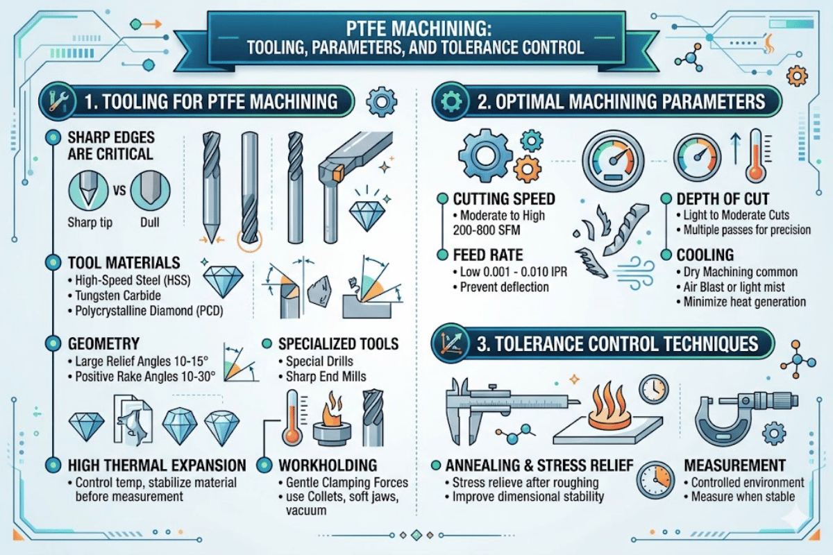
While the material is more sensitive to tooling than most engineering plastics, extreme dullness does not shear the PTFE clean; rather, it abrades, “cold flowing” the material forward and causing heat build-up that detracts from the dimensional accuracy and surface finish. There are three levels of tooling in the practical machining of PTFE:
| Tool Material | Rake Angle | Best For | Limitation |
|---|---|---|---|
| HSS (High-Speed Steel) | +10° to +18° | Low-volume, prototypes — easy to resharpen to razor edge | Wears faster on long production runs |
| Uncoated Carbide | +8° to +15° | Production turning and milling — consistent edge retention | Avoid coated carbide (coating creates drag on soft PTFE) |
| PCD (Polycrystalline Diamond) | +12° to +18° | Filled PTFE grades (glass-filled, carbon-filled) — fillers are highly abrasive | Higher tool cost; justified only for abrasive grades |
Positive rake angles are less resistant to cutting and aid the tool to shear rather than push the material. Engineers often report problems with the re use of coated carbide inserts from the machining of metals – the coated surface is ten times more resistant to friction than Teflon’s already low coefficient, leading to material building up on the edge and poor chip evacuation.
In some of the more advanced uses of HSS tooling on PTFE, an extremely sharp high polished cutting edge can be obtained by grinding the tool on a surface grinder and then rolling the burr up with a hardened drill rod. Better surface finish can be achieved with this method.
PTFE is a thermoplastic; it is a thermal insulator- the heat generated by friction while cutting stays at the tool-workpiece interface, rather than conducting (flowing) into the blank material. This refers to the fact that when improper speeds and feeds are used, the material at the cut zone will soften, gum up, and have a dimensional swell. The following values, drawn from various fabrication guides provided by different industries and machinist experience, are several spans across tolerable and productive removal rates:
| Operation | Surface Speed | Feed Rate | Depth of Cut | Coolant |
|---|---|---|---|---|
| CNC Turning (roughing) | 200–500 fpm (60–150 m/min) | 0.005–0.010 ipr (0.13–0.25 mm/rev) | 0.020–0.060 in (0.5–1.5 mm) | Air blast or dry |
| CNC Turning (finishing) | 400–800 fpm (120–240 m/min) | 0.001–0.004 ipr (0.025–0.10 mm/rev) | 0.002–0.010 in (0.05–0.25 mm) | Air blast or spray mist |
| CNC Milling | 200–500 fpm (60–150 m/min) | 0.003–0.008 ipt (0.08–0.20 mm/tooth) | 0.020–0.080 in (0.5–2.0 mm) | Air blast; climb milling preferred |
| Drilling | 600–1,000 RPM (hole ≤ 15 mm); 400–600 RPM (hole > 15 mm) | 0.005–0.009 ipr (0.13–0.23 mm/rev) | Peck drilling for depths > 2× diameter | Air and spray mists |
In most cases, higher feed rates are better than higher spindle speeds: thicker chips carry the heat away from the work into the swarf instead of into the part. A lower number of cuts per inch results from higher feed, resulting in a smaller number of thermal cycles experienced by the surface layer of the work.
PTFE does not require flood coolant at surface speeds below 500 fpm. Above 500 fpm, a light mist of non-aromatic, water-soluble coolant or compressed air should be used for temperature control. Avoid petroleum-based coolants on parts destined for food-contact, medical, or semiconductor applications — residual hydrocarbons can contaminate the finished surface and compromise chemical inertness.
Dimensional tolerances are the primary challenge in PTFE machining. Machined PTFE parts carry residual internal stresses from the cutting process itself — and those stresses release over hours and days, warping the part well after it leaves the machine. Tolerances of ±0.13 mm (±0.005 in) are achievable without special treatment. Tighter tolerances — down to ±0.025 mm (±0.001 in) — require a disciplined annealing protocol between machining operations, as documented in ASTM D3297 (Practice for Molding and Machining Tolerances for PTFE Resin Parts).
📐 Engineering Note: Multi-Stage Annealing Protocol
The gold standard for precision PTFE components follows a three-pass approach:
Annealing temperature reference range: 260–280 °C for maximum stress relief (per Eng-Tips engineering forum data and Boedeker fabrication guidelines). The lower temperatures above are for intermediate stress relief between cuts.
Annealing sequence matters as much as annealing temperature. A common mistake is to anneal only after final machining — by then, the residual stresses from roughing have already caused irreversible distortion. Re-annealing prior to the fine-machining process, rather than just at the end, relieves tool-induced tension in the residually-stressed plastic and ‘sets’ dimensional stability.
Yet equally important in dimension measurement accuracy is…the control of temperature during measurement, as you frequently can get a dimensional deviation within a specified tolerance by changing measurement temperature. Because PTFE has a crystal phase transition at the temperature near 19–20 °C, a part measured at 18 °C and re-measured at 22 °C would be seen to have a dimensional deviation often greater than the allowed tolerance. All final quality control inspections should be performed in a temperate controlled environment maintained at either the standard test environmental temperature of 20 °C or one which corresponds to the expected service conditions.
Allow PTFE stock to equilibrate with ambient in your shop for at least 24 hours before machining. Since PTFE is a very poor thermal conductor, internal temperatures may take hours to equalize with the outside cooling rate after the stock has been pulled from storage shelves, a truck bed, or an enclosed warehouse.
PTFE produces soft, stringy burrs that resist conventional deburring. Unlike metal burrs that snap off cleanly, PTFE burrs deform under pressure and re-form after removal. Manual scraping with a sharp blade removes them temporarily, but the burrs often reappear as the material relaxes — a behavior that catches machinists off guard when they first work with the material.
Cryogenic deburring is the most reliable method for PTFE parts. Parts are cooled to approximately -70 °C to -100 °C using liquid nitrogen or CO₂, making the normally pliable PTFE burrs brittle enough to tumble or blast off cleanly. This approach is standard for high-volume PTFE seal and gasket production in the aerospace industry.
Surface finishes of Ra 0.4–1.6 µm are achievable on virgin PTFE with sharp carbide or PCD tooling at finishing speeds (400–800 fpm). Filled grades tend to produce rougher finishes due to filler particle pullout — expect Ra 1.6–3.2 µm on glass-filled PTFE without post-machining polishing.
Polymer material that is more agreeable for machined parts exists: PEEK and Acetal, sold as Delrin, make good comparators. Choosing the more appropriate machinable plastic involves critical weighing of properties such as chemical resistance, dimensional stability, temperature range, friction, and machinability.
| Property | PTFE | PEEK | Delrin (Acetal) |
|---|---|---|---|
| CTE (× 10⁻⁶/°C) | 100–200 | 47–54 | 85–110 |
| Tensile Strength | 25 MPa | 100 MPa | 70 MPa |
| Max Service Temp | 260 °C | 250 °C | 100 °C |
| Chemical Resistance | Inert to nearly all chemicals | Good (not HNO₃ or H₂SO₄ concentrated) | Moderate (sensitive to strong acids) |
| Coefficient of Friction | 0.05–0.10 | 0.35–0.45 | 0.20–0.35 |
| Machinability | Requires annealing for tight tolerances; soft, deforms under clamping | Machines well; holds dimensions under load | Easiest of the three; stable, predictable chip formation |
| Creep Resistance | Poor — cold flows under sustained load | Excellent | Good |
✔ Choose PTFE When
⚠ Consider PEEK or Delrin Instead When
For applications where both low friction and high dimensional stability are desired, including filled PTFE grades (glass-filled or carbon filled) may work as an inexpensive compromise. According to NASA technical research, filled PTFE composites can reduce the coefficient of thermal expansion by a factor of up to 6× in the coefficient of thermal expansion vs virgin PTFE, coming close to aluminum in dimensional stability while maintaining much of the original PTFE properties.
Designing parts for PTFE machining means accepting the material’s particular characteristics upfront rather than discovering them on the shop floor. The following advice relates to virgin and filled PTFE grades machined from stock shapes — rod, sheet, tube, and molded blanks.
For projects requiring precision PTFE CNC machining, sharing your design file early allows the machining team to flag tolerance or fixturing concerns before production starts — preventing rework that adds both cost and lead time.
Need Precision PTFE Parts?
Le-Creator manufactures custom PTFE components with our own annealing, and quality control. Submit your design file for a free engineering evaluation.
This guide synthesizes PTFE machining data from NIST measurement research, ASTM tolerance standards, peer-reviewed machining studies, and documented machinist experience across multiple industry forums. Le-Creator produces precision PTFE machined parts at its Shenzhen facility, serving medical, semiconductor, and industrial clients. Where data comes from our production experience, it is identified as such. Where values represent industry-wide ranges, sources are cited inline.