

Supportive, Professional, Client-Focused Service
From prototypes to full-scale production, we’ve got you covered.


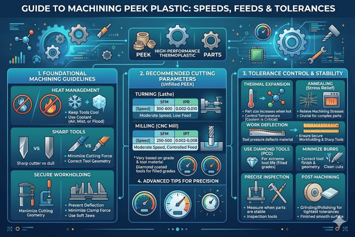
How to Machine PEEK Plastic — Speeds, Feeds, Tooling, and Tolerance Control
| Parameter | Value |
| Melting Point | 343 °C (649 °F) |
| Glass Transition Temperature | 143 °C (289 °F) |
| Continuous Service Temperature | 250 °C (482 °F) |
| Tensile Strength (unfilled) | 100 MPa |
| Coefficient of Thermal E×pansion | 45–55 ppm/K (below Tg) |
| Thermal Conductivity | 0.25 W/m·K |
| Recommended Tooling | Uncoated carbide / PCD |
| Achievable Tolerance | ±0.05 mm (±0.002 in) |
Peek is one of the most machinable engineering thermoplastics—and the most challenging to machine properly. This overview addresses machining PEEK from the perspective of the material, and includes information on choosing a cutting tool through the finishing pass, with parameter tables, annealing schedule, and tolerance guidelines culled from research journals, resin producer datasheets, and shop floor e×pertise. If you are machining unfilled rod stock or glass- filled blank, what follows will help you prevent distorted parts, melted surfaces, and blown tolerances.

Polyether ether ketone (PEEK), is a semi crystalline thermoplastic melting at 330-340 oC with a crystallinity of 20-48%, the level of crystallinity being influenced by processing conditions and whether the stock had been annealed following manufacture. This polymer is part of the polyaryletherketone (PAEK) family of polymers. Commercialized by Victrex in the early 1980s PEEK is a strong black thermoplastic showing exceptional chemical resistance high-performance mechanical properties at elevated temperatures and biocompatibility.
This makes it a direct metal-replacement candidate in aerospace, medical and oil-and-gas uses including injection mold components where high temperature stability is essential.
The numbers show why machinists have a hard time with PEEK. Its melting temperature is 343 C (649 F) and its glass transition temperature is 143 C (289 F). The Victrex PEEK 450G datasheet has a lot of other useful information, but the most important to the machinist are probably the thermal properties.
Its thermal conductivity is 0.25 W/mK. Now compare that to aluminum at 205 W/mK—It conducts at around 820 th’s as well. So heat created in the shear zone cannot dissipate heat through the workpiece the way it does in metals.
It stays put, right where you don’t want it: on your cutting tool.
PEEK will produce stringy, continuous chips rather than the segmented chips you get from metals or even acetal. Those strings can wrap around tooling, re-weld to the workpiece surface, and ruin surface finish if not cut away. And as PEEK is elastic at cutting temperatures it will spring back after the tool has passed—so your measured diameter or bore can be different than what you’ve programmed.
The National Institutes of Health (PMC7796128) reports that PEEK machinability can vary widely depending on filler content and cutting parameters. It’s worth knowing this material know-how if you intend to CNC machine production PEEK.
Take-away point:Compared to other plastics used in machining,PEEK has quite a low value of thermal conductivity 0.25 W/mK. This may cause heat to not escape at the cutting interface, in addition elastic spring-back alters the finished component geometry. Both of these phenomena require the tool, parameter and process response responses be altered.
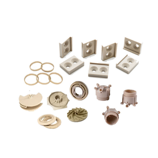
All PEEK grades machine differently. The grade – in particular the filler type and loading % – affects tool life, surface finish achieved and parameter windows. Using the wrong parameters for a filled grade is a usual cause of early tool failure and scrap.
| Grade | Filler | Tensile Strength | Max Service Temp | Tool Wear Impact | Typical Applications |
|---|---|---|---|---|---|
| Unfilled / Natural | None | 100 MPa | 250 °C | Baseline (1×) | Seals, bearings, insulators |
| GF30 (30% glass fiber) | Glass fiber | ~160 MPa | 250 °C | 2–3× faster wear | Structural brackets, pump components |
| CF30 (30% carbon fiber) | Carbon fiber | ~210 MPa | 250 °C | 3–5× faster wear | Aerospace fittings, high-load bushings |
| Medical-grade (per ASTM F2026) | None (ultra-pure) | 100 MPa | 250 °C | Baseline (1×) | Spinal cages, dental implants |
Industry practices seem to indicate that glass-filled PEEK wears carbide cutting tools 2-3 times faster than unfilled grades. Nothing is said about carbon-filled PEEK, this material is even much worse—the fibers behave like micro-abrasives, grinding the cutting edge at every cycle. Filled-grade machining demands diamond tools — PCD or diamond-coated inserts for anything but ‘ditcher’/short production run.
Surface finish is another grade variation. as documented in PMC7796128 Achievable surface roughness of 0.6-3.0 m Ra on unfilled PEEK with machining conditions: turning. Unfilled grades finish slightly smoother under consistent turning parameters, likely because fibers separate more cleanly from the surface versus being pulled out.
📐 Engineering Note
Medical-grade PEEK demanded ASTM F2026 compliance and operations within a sealed controlled environment (dedicated tooling, coolant system separation, particle management), facilities requirements for the final implant.
Le-creator’s machining PEEK material service provides unfilled, GF, and CF stock with grade-specific process controls.
Main point: filler type is what influences tooling and process parameters. Green unfilled PEEK is the softest, mineral-reinforced is the hardest. Pick the right tooling for the grade, then determine optimal settings.
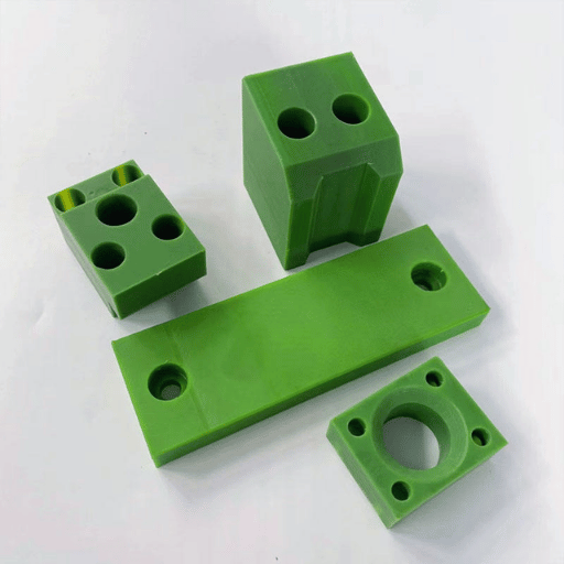
Tool selection for PEEK is based on the grade being machined, feature geometry, surface finish requirements. Failure to choose the correct tooling causes more scrap on PEEK jobs than incorrect speeds/feeds because selecting the best tool entirely defines the heat level and chip flow.
Carbide (off the shelf fine grain uncoated carbide) is effective at machining unfilled PEEK. Silicon carbide (SiC) tooling is ideal for the natural grades, withstanding the moderate abrasive nature of the polymers. For GF30 and CF30 grades, a PCD (polycrystalline diamond) or carbide tool with a diamond coating offers the best wear life – under 10 parts and HSS is quickly dulled, per one industry commentator who supplied a horrifying picture of a just-sharpened drill dull within a small handful of holes.
Edge radius should be 0.01-0.02 for the most effective results with minimal burr formation. PEEK deforms rather than shears with a blunt tool. A rake angle of 0-6 positive provides good turning performance. In milling, a 10-15 positive rake angle helps prevent pressure against the cutter and encourages chip flow through the cut.
Single-flute end mills are recommended for features requiring a very thin wall (less than 1.5 mm), as they reduce pressures on the tool through each revolution.
Coating PEEK tooling with carbide caused material smear as the coating created friction and heat on contact with the polymer, and if clamped, a streaky glazed surface on unfilled PEEK. If the silver streaks in the surface, the coating is the problem.
Le-creator’s CNC machining service runs carburized and PCD tooling for PEEK jobs.
Okeyou: Match uncoated carbide to unfilled PEEK, make sure edge radius is under 0.02 mm, and use positive rake angles. Use single-flute end mills on walls thinner than 1.5 mm.
Speed and feed rates for PEEK machining are very different from typical commodity plastics such as nylon or acetal. Not only are the parameter windows for maximum and minimum ranges tighter, the consequences of operating outside of those windows are much higher, and filled grades also require even lower values. The 3 tables below cover the 3 most common PEEK CNC operations—turning, milling and drilling.
| Parameter | Unfilled PEEK | Glass-Filled (GF30) | Carbon-Filled (CF30) |
|---|---|---|---|
| Cutting Speed | 50–100 m/min | 35–70 m/min | 30–60 m/min |
| Feed Rate | 0.05–0.15 mm/rev | 0.05–0.10 mm/rev | 0.05–0.10 mm/rev |
| Depth of Cut (rough) | 1.0–3.0 mm | 0.5–2.0 mm | 0.5–1.5 mm |
| Depth of Cut (finish) | 0.1–0.5 mm | 0.1–0.3 mm | 0.1–0.3 mm |
| Parameter | Unfilled PEEK | Glass-Filled (GF30) | Carbon-Filled (CF30) |
|---|---|---|---|
| Cutting Speed | 50–100 m/min | 35–70 m/min | 30–60 m/min |
| Feed per Tooth | 0.05–0.15 mm | 0.03–0.10 mm | 0.03–0.10 mm |
| Depth of Cut | 0.5–2.0 mm | 0.3–1.0 mm | 0.3–1.0 mm |
| Parameter | Unfilled PEEK | Glass-Filled (GF30) | Carbon-Filled (CF30) |
|---|---|---|---|
| Cutting Speed | 30–60 m/min | 20–40 m/min | 20–40 m/min |
| Feed Rate | 0.05–0.10 mm/rev | 0.03–0.08 mm/rev | 0.03–0.08 mm/rev |
| Peck Depth | 1× drill diameter | 0.5× drill diameter | 0.5× drill diameter |
Most important conclusion of the PMC7796128 study: cutting velocity explained 61.3% of machining force variation observed in unfilled PEEK, and an even higher 83.6% for GF30! Spindle speed dominates other parameters by far. Small parameter changes lead to large differences in machining force, temperature, and surface characteristics.
Counterintuitive but well-documented fact: for PEEK, raising the feed rate can lower temperature build-up. With a higher feed, more material passes the cutting tool each revolution so it transports more thermal energy in the chips away from the cutter. Running too gently and so lightly that the chips aren’t completely formed creates a work surface of excess frictional heat without copious removal of the energy producing it.
Be conservative to start. Raise the feed rate gradually—the non-linear response of PEEK to machining parameters will surprise you. Yellowing or smearing to the work piece surface are manifestations of excess heat—ditch it immediately! Drop the spindle speed or increase the feed rate if necessary, but don’t do both simultaneously.
📐 Engineering Note
Start values were compiled from Drake Plastics, Ensinger and other published sources. Your force, temperature, chip shape and surface will vary based on machine and material differences. Make test cuts before beginning production—especially when going between unfilled and filled.
Shops without the luxury of a dedicated PEEK cutting tool set can cut trial and error time substantially by working with the expert—Le-creator runs precision CNC machining on PEEK every day and has validated parameters for each grade.
Prime takeaway: Cutting speed governs 61-84% of force variation when machining PEEK. Keep it low, boost feed rate before spindle speed, and yellowing is the primary indicator of temperature strength.
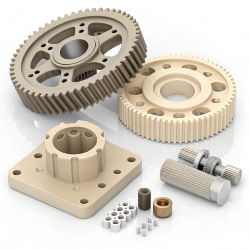
When machining PEEK keep in mind: your coolant needs will be counter to metal machining intuition, as most machinists reach for flood coolant. This is in fact not advised, as liquid under temperature differential stress will tend to cause micro-crack formation in the surface, perhaps imperceptible to the eye at time of formation but prone to fail during load or fatigue cycling conditions.
The best method to avoid thermal shock is compressed air directed at the works. It does not change the temperature as rapidly as water or mist based coolants, while clearing away chips. When additional cooling is desired for vertical deep-pocket jobs, small still humidity controlled coolant mists with no oil to penetrate the PEEK surface are appropriate.
PEEK’s coefficient of thermal expansion (CTE) adds another layer. 45-55 ppm/K below the glass transition temperature, PEEK expands about twice as much as aluminum (23 ppm/K). You are looking at 0.011-0.014 mm of growth for every 10 C rise in temperature during machining just on a 25 mm diameter part—something to consider when your tolerance budget is 0.05 mm. Remember: temperature stability is a dimensioning requirement, not just a surface finish one.
Flood coolant on PEEK causes thermal shock— and can promote micro-cracks. Use compressed air for chip-clearing and heat removal. Use mist coolant only when necessary and only with water-based solutions.
Chip control is far more important than cooling in PEEK cutting operations. Stringy PEEK chips tend to wrap around the cuttings tools and weld to the workpiece if not continuously cleared. Position your high pressure air blast to blow chips away from the cut, not farther into it.
The conclusion: Avoid flood coolant on PEEK. Use compressed air exclusively for chip removal and heat removal. Use mist coolant, but only if theair does not do the job alone.
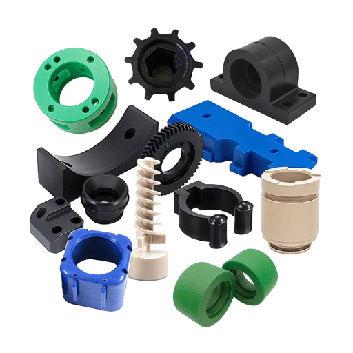
Annealing: Common, critical step often overlooked. Nothing mis-aligns finished PEEK parts and causes them to go out of tolerance faster than skipping the anneal. Extruded rods and plates have residual stresses from the extrusion process. When you cut through those stresses unevenly, they beak loose and cause the part to warp. Annealing relieves those warping stresses before they measurably distort the part.
There are three situations where annealing is required:
Boedeker Plastics has established an annealing cycle for PEEK:
📐 Engineering Note — PEEK Annealing Schedule
Stage 1: Ramp oven to 300 F (149 C) over 2 hours. Hold at 300 F for 60 minutes for every 0.25 inches (6.4 mm) thickness.
Stage 2: Ramp oven to 375 F (191 C) over 2 hours. Hold at 375 F for the same time determined in stage 1.
Cooling: decrease temperature at 50 F (28 C) per hour until room temperature is reached. Do not open the oven door during cooling, as the unbalanced airflow causes stratification.
Example—part with 1″ (25.4 mm) wall thickness has a hold time of (4 hours). A part with 0.020″ (0.5 mm) wall thickness needs 0.5 hours in each stage.
The entire cycle for a 1-inch thick part takes about 18-20 hours, including ramp up and ramp down. That’s a long lead time— but you would have to machine a finished part, observe warping occur overnight, then scrap the part and face the associated loss of machine time, waiting for an annealed precast to be machined again. Le-creator’s closed-loop plastic machining cycle saves lead time by defaulting to annealing for all tight-tolerance PEEK jobs.
Important takeaway: Always anneal your extruded PEEK stock before machining. For tight tolerance parts, anneal after roughing-anneal again after finishing. Follow the Boedeker 2-stage ramp cycle and cool at no more than 50 F/hr.
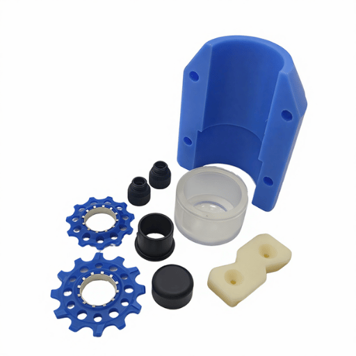
Use of PEEK extrusion stock- always anneal. For tight tolerance parts- anneal after roughing and after finishing. Use Boedeker two-stage ramp schedule; cool at no more than 50 F/hr.
| Tolerance Level | Tolerance Range | Requirements |
|---|---|---|
| Standard | ±0.10 mm (±0.004 in) | Sharp tools, proper speeds and feeds |
| Precision | ±0.05 mm (±0.002 in) | + Annealing + temperature-controlled environment |
| High Precision | ±0.025 mm (±0.001 in) | + Post-anneal, stabilization time, 20 °C inspection |
Three levels of tolerance control are practical for PEEK machining. Once you understand the tolerance level your job demands, you can specify the right controls and avoid under- or over-engineered solutions.
Production methodology for precision PEEK components: Anneal raw stock Rough machine Re-anneal Finish machine Wait 2-4 hours at room temperature Inspect at 20 C. Desktop measuring PEEK parts directly after machining yields unreliable measurements- the PEEK must be allowed 2-4 hours to thermally equilibrate prior to measurement.
✔ Advantages of PEEK Machining
⚠ Limitations of PEEK Machining
For tight tolerance production parts, Le-creator prescribes inspection at 20 °C ±1 °C and annealing for all PEEK machining jobs by default. For the most precise work, the anneal-rough-anneal-finish protocol is normal.
Key takeaway: Anneal PEEK to control dimensions. Cool down slowly, verify at controlled temperature. Allow 2-4 hours for thermal stabilization before inspection.
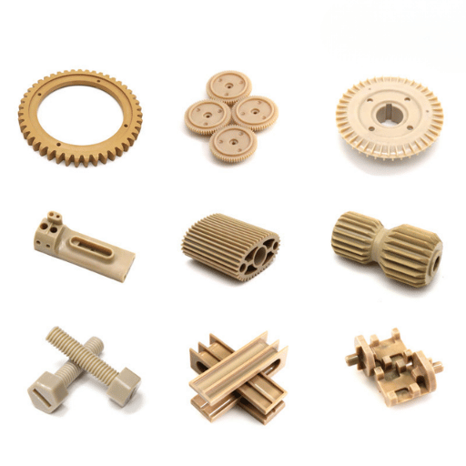
Most iterations of Le-creator CNC machine PEEK- no filler, glass fill, or carbon fill- to 0.025 mm with 17+ years of precision in-house experience. Send us your drawing, and we’ll accommodate most PEEK parts by quote within a day or two.
The parameters and technical references used in this PEEK machining guide are derived from Victrex PEEK 450G datasheets, Drake Plastics machining guidelines, a peer-reviewed machinability comparison study, and most recently a Boedeker annealing protocol. Le-creator is experienced in producing production quality PEEK to spec and tolerances- our recommendations are based on the chemistry of PEEK in three different forms: unfilled, GF30, and CF30. Hyperlinks to the data sources are included.