Supportive, Professional, Client-Focused Service
Get in touch with Lecreator Company
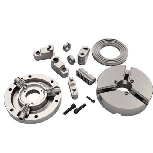
From prototypes to full-scale production, we’ve got you covered.


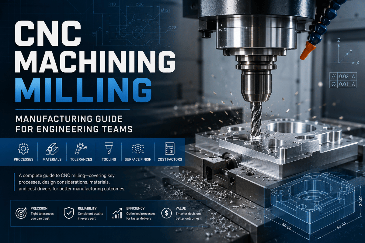
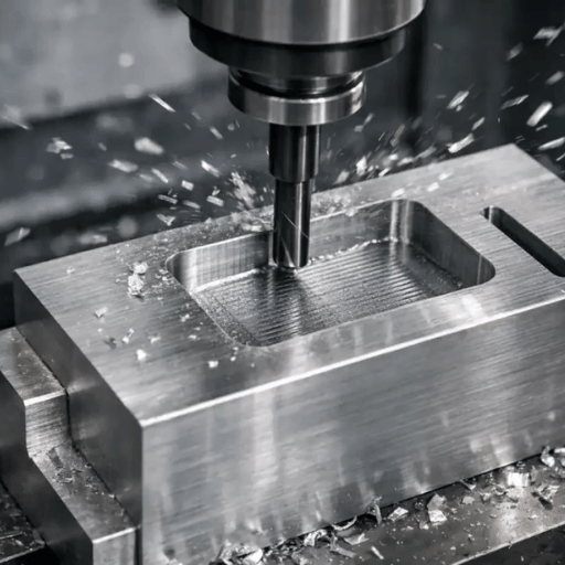
CNC machining milling is a subtractive manufacturing process that uses computer-controlled cutting bits, which spin, to trim e×cess material away from the workpiece. That technology yields precision components that, after processing, can be the tiny part of a complex aerospace assembly or medical device. Read about each aspect of the milling workflow – types of machinery, machining processes, ISO 2768 tolerance specifications, material options and validated cost standards – before a quote Request shows up for the programmer/machinist.
CNC Milling: Quick Specs
| Process type | Subtractive — rotating cutter removes material from a stationary workpiece |
| Standard tolerance | ISO 2768-m (±0.005″ / 0.13 mm) |
| Precision tolerance | ±0.001″ (0.025 mm) available on request |
| Machine axes | 3-axis (standard) to 5-axis simultaneous |
| Compatible materials | 40+ including metals, engineering plastics, composites |
| Surface finish (Ra) | 0.8–3.2 µm as-machined; 0.4 µm with fine finishing pass |
| Minimum order | 1 piece — no hard tooling required |

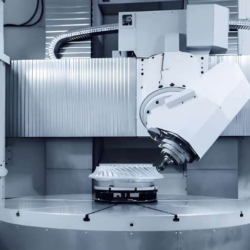
CNC milling is a Computer Numerical Control (CNC) machining operation that uses a CNC machine with a rotating cutter moving along multiple axes to achieve precise material removal from a workpiece and create the target shape. While drilling involves pushing a single-point cutting tool along a single axis, CNC milling cutters can engage with a workpiece at a multitude of angles, producing pockets, slots, bores, contoured surfaces, and intricate designs within tighter tolerances on a single fixture.
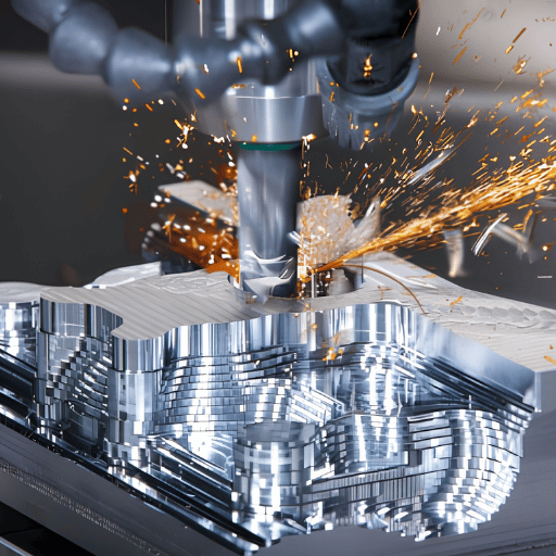
The computer numerical control is basically a G-code program that tells the spindle how fast to turn; the table or tool how fast to traverse; the direction of travel; and when to kick in the coolant. Work is chucked to a workholding surface (the machine table) or the tool is mounted into the spindle: it rapidly rotates to cut away material. The axis movements are servo-controlled (often by stepping motors as well), driving the work piece and cutting tool along the exact path designated.
To the thousandth (or whatever the programmed tolerance dictates), it should produce a part exactly like the computer design.
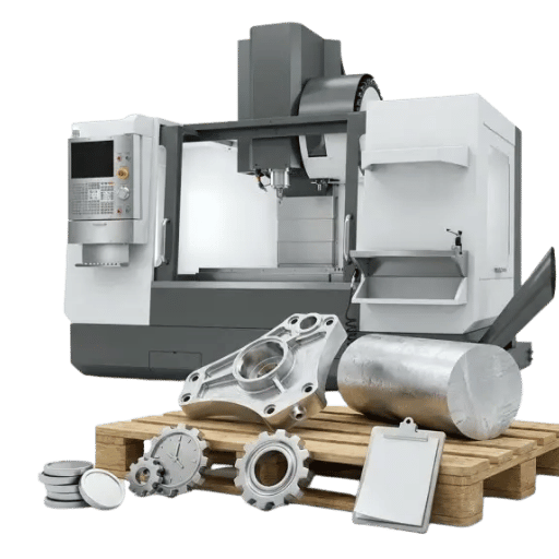
At Lecreator, a CNC milling service provider with 17+ years of manufacturing experience, 80+ CNC machines handle everything from 3-axis aluminium brackets to simultaneous 5-axis titanium aerospace components — all under ISO 9001-certified quality management.
✔ Advantages
⚠ Limitations of CNC Milling
CNC milled parts offer the lowest cost for high-featured parts, complex or non-prismatic features or components with tight tolerance specifications. However, if you only need a cylindrical shape and have little other work, CNC turning for cylindrical parts is the lower-cost route.
Milling is a manufacturing process, which translates a digital design into a finished metal or plastic component. There are four stages in the milling process, each stage has a different failure mode; knowing this in advance can save the first-article from most problems.
Engineering Note — Al 6061 Starting Parameters
For aluminium 6061, use a 4-flute carbide end mill (diameter); spindle 10k-18k RPM, feed 40-120ipm, .05-.25 depth of cut; this is just the beginning values and will change based on workholding rigidity, tool length overhang and the rigitidy of the machine. -If you increase tool overhang, you’ll need to decrease the speed by roughly same proportion to eliminate chatter.
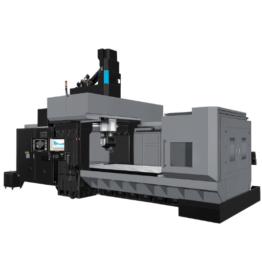
Spindle configuration (vertical or horizontal) and the number of axes (3 to 5 or more) are the two major determining features of any cnc milling machine – which greatly influence your geometric tolerances, the number of setups, and thus cost per part.
| Feature | Vertical Machining Centers (VMC) | Horizontal Machining Centers (HMC) |
|---|---|---|
| Spindle orientation | Vertical — perpendicular to table | Horizontal — parallel to table |
| Best for | Flat parts, moulds, dies, general milling in vertical machining centers | Heavy box-shaped parts, multi-face machining in horizontal machining centers |
| Chip evacuation | Fair — chips fall onto workpiece | Excellent — gravity clears chips from cut zone |
| Setup access | Easy, open table | Requires pallet changer for high efficiency |
| Cost premium | Baseline | +20–40% vs. equivalent VMC |
Axis count is the single most important specification for quoting and lead time. Use this matrix to match your part’s complexity to the correct machine configuration:
| Part Complexity | Recommended Axes | Typical US Rate | Best Application |
|---|---|---|---|
| Flat surfaces, 2D contours, prismatic features | 3-axis | $40–$80/hr | Brackets, frames, enclosure plates |
| Undercuts, partial rotation, helical features | 4-axis | $55–$120/hr | Camshafts, helical slots, indexed round parts |
| Complex 3D surfaces, ≤5 setups eliminated | 5-axis simultaneous | $80–$250/hr | Aerospace impellers, turbine blades, dental implants |
A 3-axis milling machine provides x,y,z movement; capable of accessing the top of the part, and its 2 side faces without a setup change. Other surfaces can only be approached if the part is rotated by repositioning it in a fixture or other clamp device – a 5 axis CNC machining machine has two additional rotary axes, enabling 360 degree access to the part in a single setup.
An object requiring 3 to 4 setups on a 3-axis CNC machine can typically be completed in a single setup on a 5-axis machining tool — reducing error potential by not repositioning, and saving operator time. For full details, see our guide on 5-axis CNC machining for complex components.
A six sided feature with a 5 axis CNC will eliminate unnecessary tool changes and the added tolerance stacking that comes with re-positioning.
The cost per part of a 5 axis cnc machine will usually beat the rate when the geometry required exceeds two sides, has undercut or compound angel features, in comparison to the three-axis alternative –
Every milling operation creates a different feature and is created using a specific tool – in technical print or RFQ it’s important to be explicit about which feature the part requires, not the process used by the machinists; saving wasted time and preventing you from getting quotes for features that you do not need! –
| Operation | Feature Produced | Primary Tool | Typical Ra | Application |
|---|---|---|---|---|
| Face milling | Flat datum surfaces | Shell/face mill cutter (indexable inserts) | 0.8–1.6 µm | Datum planes, mounting faces |
| Peripheral milling | Vertical walls, contours | End mill (2–6 flute) | 1.6–3.2 µm | External profiles, side walls |
| Slot milling | Slots, keyways, grooves | Slot drill / side and face cutter / end mill | 1.6–3.2 µm | T-slots, key slots, channels |
| Pocket milling | Closed cavities | End mill (roughing + finishing) | 0.8–3.2 µm | Housings, mould cavities |
| Bore milling | Precision circular bores | Boring head / interpolated end mill | 0.4–1.6 µm | Bearing seats, close-fit holes |
| Thread milling | Internal/external threads | Thread mill (single or multi-form) | 0.8–1.6 µm | M4–M72 precision thread fits |
Pro Tip — Internal Corner Radius
Many manufacturing engineers advise that the internal sharp corners are perhaps the most common design error made for milling.
Because of the roundness of a round cutting tool, the shop will always leave a round feature at any internal corner – if a 0mm round at internal corners is the design request, it will require the shop to use a miniature and very slow round tooling to achieve. Consider making the internal corner radii 1/3rd of the pocket depth of all internal corners of a milled part to allow the machinist to use a standard round tool. See our full internal corner radius design guidelines.
For features requiring threads, thread milling is superior to tapping with large-size threads and results in a better surface finish on hard-to-machine materials. See our thread milling specifications for guidance on size, pitch, and tolerances.
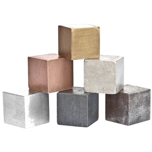
Machining time and tooling life depend heavily on material selection and cutting fluid strategy — both directly impact per-part cost. The table below ranks the seven most common CNC milling materials by machinability and relative cost multiplier. Lecreator machines 40+ materials, including exotic alloys and engineering plastics.
| Material | Machinability | Key Challenge | Recommended Coolant | Cost vs. Al 6061 |
|---|---|---|---|---|
| Aluminium 6061 | Excellent | Built-up edge at low spindle speeds | Flood (5–8% soluble oil) | 1× (baseline) |
| Aluminium 7075 | Good | Harder than 6061 — verify heat treatment state | Flood | 1.2× |
| Steel 4140 | Moderate | Tool wear; requires slower feeds | Flood + high-pressure | 2–3× |
| Stainless 316L | Difficult | Work-hardening; heat accumulation | High-pressure through-tool | 3–4× |
| Titanium Ti-6Al-4V | Difficult | Heat retention; rapid cutter failure | High-pressure through-tool (70+ bar) | 4–6× |
| PEEK | Good | Chip control; fine dust generation | Air blast / minimal flood | 2–3× |
| ABS / Nylon | Good | Softening under heat; burr formation | Air blast | 1.5× |
Engineering Note — Titanium Coolant Pressure
Machining titanium with little to no coolant results in catastrophic cutting tool failure. The rate at which Ti-6Al-4V holds heat at the cutting tool face dramatically surpasses that of even steel, with industry-standard approach for machining titanium calling for 70+ bar high-pressure through-tool coolant. Academic papers have also verified that this high-pressure coolant technique extends tool life by up to three times in Ti-6Al-4V turning applications when compared to standard flood cooling.
Make sure your vendor is aware of their machines having high pressure spindle coolant before quoting you titanium.
With stainless steel CNC machining, work-hardening becomes the real issue: always make sure that the tool is continuously engaged – that the tool never dwells in the cut. That will keep the newly-formed work-hardened layer of steel from turning and dulling the tool. Refer to the aluminium machining tolerance guide for tolerancing of specific parts made from aluminum.
CNC milling can consistently achieve tight tolerances – as long as the required tolerance was entered correctly onto the drawing. If tolerances were omitted from a dimension the manufacturer is free to assume a default value that does not necessarily correspond to the functional requirement of the feature. The ISO 2768 is the specification for default tolerance values for general CNC machined parts.
| Class | Symbol | Linear Tolerance ±mm (30–120 mm range) | Typical Application |
|---|---|---|---|
| Fine | f | ±0.1 | Precision assemblies, close-fit bearings |
| Medium (default) | m | ±0.2 | General CNC machined parts — Lecreator standard |
| Coarse | c | ±0.5 | Large structural parts, simple features |
| Very coarse | v | ±1.0 | Rough machining, non-critical dimensions |
Lecreator’s standard output is ±0.005″ (0.13 mm) ISO 2768-m on all orders. For bearing bores, press-fits, and aerospace interfaces, ±0.001″ (0.025 mm) is achievable on request. Features below ±0.0005″ require a temperature-controlled measurement lab and specialised gauging.
| Ra Value | Condition | Typical Application |
|---|---|---|
| 3.2 µm (125 µin) | Standard as-machined | Structural, non-sealing surfaces |
| 1.6 µm (63 µin) | One finishing pass | Sealing surfaces, general assemblies |
| 0.8 µm (32 µin) | Fine finishing pass | O-ring grooves, hydraulic interfaces |
| 0.4 µm (16 µin) | Multiple finishing passes | Medical implants, optical-grade surfaces |
Manufacturing engineers have learned over and over again that singling out the nominal dimension of the part – without the required tolerance – is the one most obvious, yet seemingly most elusive cause of remaking a part on a milling machine. The ISO 2768-M should be your standard reference, call out the exception only if it’s absolutely necessary for the function.
For detailed tolerance benchmarks across processes, see our tight tolerance machining benchmarks article.
The CNC milling cost is determined by machine time, material, setup and any subsequent operations.Belowis our 2025-2026 benchmark pricing by type of machine shop in both the USA and in offshore China – these are the actual benchmark figures that the machinists will use in their CNC mill cost estimates.
| Machine Type | US Shop Rate | Offshore Rate (China) | Best Scenario |
|---|---|---|---|
| 3-axis VMC | $40–$120/hr | $8–$25/hr | Brackets, housings, plates |
| 4-axis | $55–$130/hr | $12–$35/hr | Camshafts, helical features |
| 5-axis simultaneous | $80–$250/hr | $20–$60/hr | Aerospace impellers, medical implants |
| Swiss CNC | $60–$150/hr | $15–$45/hr | Precision small parts <25 mm diameter |
Total Part Cost Formula:
Total Cost = Machine Hourly Rate + Material + Setup Charges ($50-$200) + Surface Treatment + Shipping.
5 common design modifications that usually reduce 20-40% of per-part cost:
Ready to run the numbers? Request an instant CNC milling quote — upload a STEP file and receive a DFM-reviewed price within 24 hours. For 1–5 piece early-stage designs, see our rapid CNC prototyping service with no minimum tooling cost.
As CNC milling machines have become more capable over the past decade, its share of global production for five major product types has increased in recent years.
Structural brackets, impellers, and housings in Al 7075 and titanium Ti-6Al-4V. Aerospace components require AS9100 traceability and first-article inspection reports. Lecreator delivers ISO 9001-certified parts with full material mill certifications on request. For more on aerospace requirements, see our aerospace CNC machining requirements guide.
Engine components, gearbox housings, and brake calipers demand high-volume repeatability within ±0.02 mm across production runs. CNC milling bridges the gap between prototype validation and die-cast production tooling commitment — keeping options open while the design evolves. Read more on automotive CNC milled components.
Implants, surgical instruments, and enclosures in titanium Grade 23 and 316L stainless steel. FDA-traceable material certifications and surface finishes of Ra <0.8 µm are standard requirements. See our medical device CNC machining capabilities for full traceability documentation requirements.
If you need high volume, cost effective housings and heat sinks made from Anodised AI 6061 and want to include feature with thin walls up to 0.8-1.5 mm without supporting structure as a good rule of thumb maintain the height-thickness ratio below 8:1 then cnc milling is one great option for those designs.
CNC milling allows us to rapidly create your first article parts within 3-7 business days (at no tooling cost!), this is why it’s our standard manufacturing process no matter the industry. You save as much as 30-60 percent on your per-part price beyond ten units per project due to the amortized setup cost across a given order.
The global milling machine market is valued at $21.68 billion in 2025, and is projected to reach $45.41 billion by 2034, growing at roughly 8% per year.
This growth will be driven by industries demanding ever-tighter precision, including EV powertrain components, aerospace structures, and medical devices. Three changes are expected to occur in CNC Precision Milling in 2025-2026;
1. Expanding role of the 5-Axis Mill-5-axis technology has broadened the range of applicable models outside those manufactured strictly for aerospace prime contractors.
Small to medium sized shops in china and other areas in Southeast Asia since last year are adopting5-axis equipment. Many designs that previously needed to accommodate 3 or 4 set ups on a 3-axis machine now completed with only one single setup, enabling more intricate parts at significantly increased levels of dimension accuracy and with reduced lead time for Buyers. For complicated geometries, whether your Supplier offerssimultaneous 5 axis machine tool or 3+2 positioning, it’s worth inquiring.
2. AI-Assisted Toolpath Optimisation. Advanced CNC software and AI-powered CAM tools are now integrated into production platforms, enabling automated toolpath generation and new milling techniques for chatter prediction and thermal drift compensation in real time.
In practical terms this translates to higher surface finish results on intricate 5-axis movements along with reduced programming time on any given job. Buyers can ask suppliers whether their CAM programmes use adaptive control loops to verify toolpaths before and during cutting. For high-speed approaches, see our overview of high-speed CNC machining techniques.
3. Lights Out Machining and Automation This is when parts can be automatically swapped to and from machine tending robot systems and 24 hour cells through automated pallet changers. For any parts running repetitively, this automation approach can shorten a lead time from an typical 5-7 working day to just 2-3 days.
This is clearly most visible in Aerospace and Medical components where repeat rates are high despite a small batch sizes. When considering your production partner, you should enquire about their automated cell capacity.
Buyer Action: When seeking 5 axis,ISO 9001, and high precision capabilities for complex parts in 2026, look carefully beyond just the axis count on supplier capability data-base information as automated solutions from offshore facilities are reducing the traditional time penalties.
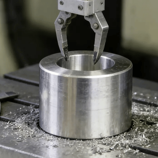
CNC milling uses a rotating multi-point cutting tool which is moved over a workpiece, which is typically stationary, although can rotate on some types.
CNC turning uses the workpiece rotated on a mandrel or between centers against a single point tool. CNC milling is ideal for flat features, pockets, complex surfaces and square features on prism shapes. Turning is well suited for cylindrical surfaces and turning internal diameters, along with complex rounded shapes on the outside.
Many precision parts rely on both milling and turning in sequence: milled for flat and pocket features, turned for bores or external diameters. For a full comparison, see our CNC Milling vs CNC Turning guide.
PrecisionCNC Milling Capabilities Precision Call Outs and Material Grades As standard CNC turning will maintain to a tolerance of ± 0.005 inches (0.13mm). Close Tolerances can achieve ± 0.001 (0.025 mm) at little additional expense.
Achieving ultra-tight tolerances of ± 0.0005 (0.013 mm) requires carefully controlled environments, dedicated testing equipment and careful consideration of your inspection plans and can incur extra cost. CNC milling is well suited to meet high precision machining requirements.
CNC Cutting tool specification Choosing the correct cutting tool requires understanding three key elements. The most important of these is: Material: Carbides for most metals such as steel and stainless. HSS will suffice for very soft materials.
Flute count: 2-flute cutters can have more chip-clearing capabilities and remove heat better than 4-flute cutters in materials such as aluminum and plastics. The number of flutes increases tool stiffness for materials such as steel. Coatings:TiAlN is suitable for all steels and stainless steel, whereas for aluminum, ZrN or no coating would work.
An incorrect match of cutting tool and materials results in excessive wear and poor surface finish.
3D geometry for your part comes from your CAD (computer-aided design) software. This geometry is then fed into your CAM (computer-aided manufacturing) software, which tells the CNC the exact move of every cutter, spindle speed, feed rate, and depth of cut, which then is posted out as G-code. Mistakes in your CAM set up, ( incorrect stock allow-ances , or incorrectly set tool offsets or turning tools without collision detection ) show up as dimensionally incorrect parts.
Yes. There is no hard tooling for CNC milling, so the break-even occurs from day one with turn-around time for first articles typically 3-7 business days. There’s a definitive cost crossover at quantities of 10+, where the cost-per-part can drop by 30-60% as the setup charge is amortized across multiple parts.
At very high quantities above 1,000 parts, provided geometries are simple, die-casting or injection molding is more competitive. However, where complex geometries are required to tight-tolerances at all quantities, CNC is king.
Three challenges dominate CNC milling: tool chatter, workholding instability, and thin-wall deflection. Chatter is the most prevalent, stemming from insufficient rigidity in either the workpiece fixture or the toolholder. The forums consistently flag thin-wall pockets (walls < 1.5 mm, height-to-thickness ratio above 8:1), but these issues are addressed by proper tooling support and solid fixturing.
Upload your cad file for DFM check in the cnc milling quotation, receive within 24hours, ISO 9001 standard. No MOQs.
Editorial Transparency
This article was generated by Lecreator engineering and content team at Shenzhen Le-creator Technology Co., Ltd. Tolerance figures, machine throughput data, and yields represent Lecreator performance (2025) and may not be suitable as an industry standard. Market size is based on a report by Fortune Business Insights.
The ISO 2768 tolerance class is based on the ISO 2768-1:1989 international standard. Machining costs figures is based on reported ranges; individual shop rates will differ based on region, capacity, utilization and part complexities.