Supportive, Professional, Client-Focused Service
Get in touch with Lecreator Company
From prototypes to full-scale production, we’ve got you covered.


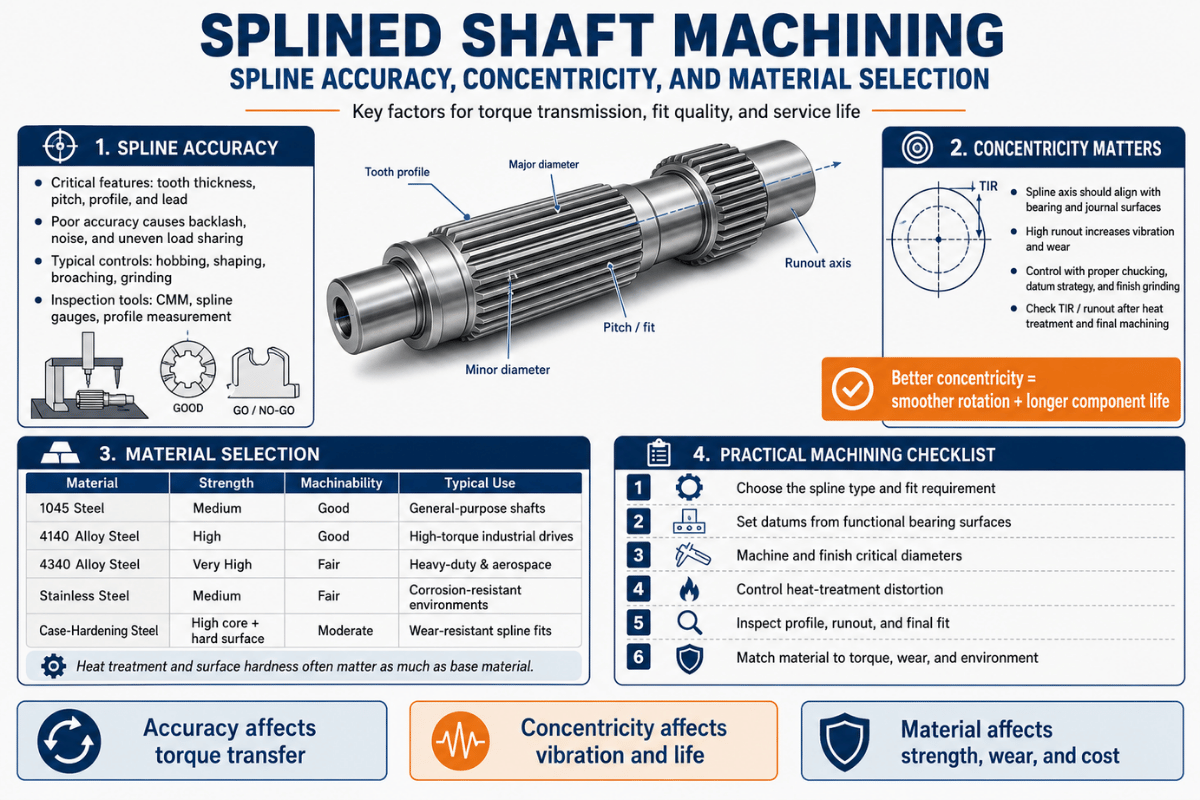
Splined shaft machining is the process of cutting a series of teeth, ridges, or grooves along a shaft so it can transmit torque to a mating hub while holding alignment, and the three things that decide whether the part work are spline accuracy, concentricity, and material selection. Get the fit class right, hold the spline true to the bearing journals, and pick a steel and heat treat that survives the load, and a splined shaft outlasts the assembly around it. Miss one, and you get backlash, fretting, or a part that won’t assemble. This guide walks through the methods, standards, and decisions a working machinist or buyer actually has to make.
| Governing standards | ANSI/ASME B92.1 (inch) · ANSI B92.2M / ISO 4156-1/2/3:2021 (metric, side-fit) · DIN 5480 (reference-diameter) · JIS D 2001 |
| Spline forms | Involute · straight-sided (parallel) · serrated · helical · crowned · ball |
| Centering / fit | Side (flank) fit, major-diameter fit, minor-diameter fit |
| Common materials | 8620, 4140, 4340, 1045, 17-4 PH stainless |
| Cutting methods | Hobbing, broaching, shaping, milling, scudding/power skiving, cold rolling, grinding, wire EDM |
| Inspection | Composite GO / element NO-GO gauges, measurement over pins, CMM (per ISO 4156-3) |
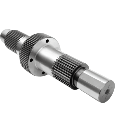
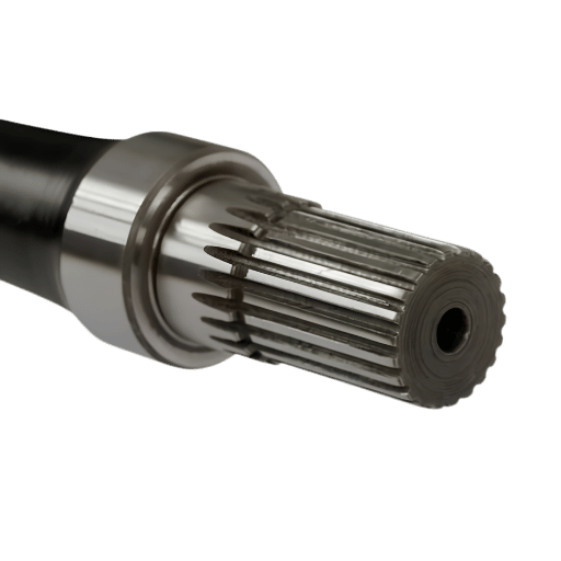
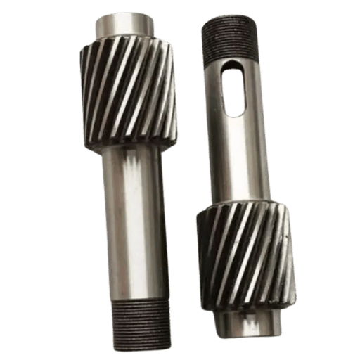
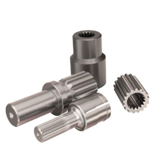
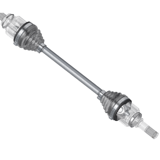
A splined shaft is a cylindrical shaft with multiple teeth (the splines) cut parallel to its axis that mesh with matching grooves in a mating part, a gear, hub, or coupling, to transmit torque and keep the two parts aligned. Unlike a single key in a keyway, the splines spread the load over many teeth, so the same shaft diameter carries far more torque, runs with less stress concentration, and can let the hub slide axially while still driving it.
That sliding ability is why drive shafts, transmission shift mechanisms, and collapsible steering columns use splines rather than keys.
Settle the spline form first, because it drives the cutting method, the standard, and the cost. The table below clusters the forms you’ll actually be asked to make.
| Spline form | Tooth profile | Governing standard | Typical use |
|---|---|---|---|
| Involute (30°) | Curved involute flanks, self-centering | ANSI B92.1 / ISO 4156 / DIN 5480 | Auto transmissions, gearboxes |
| Involute (37.5°) | Higher pressure angle, stronger root | ANSI B92.1 / ISO 4156 | High-torque, compact splines |
| Involute (45°) | Shallow, many teeth | ANSI B92.1 (fillet root) | Fine-pitch, small diameters |
| Straight-sided (parallel) | Flat, parallel flanks | SAE / ISO 14 (older) | Agricultural PTO, low-speed drives |
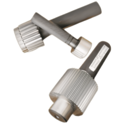
| Serrated | V-shaped 45°/60° teeth | SAE J498 | Adjustment knobs, press-fit positioning |
| Helical involute | Angled involute teeth | ISO 4156 (helical annex) | Smooth high-speed torque transfer |
| Crowned | Barreled flank along length | Per drawing / OEM | Misalignment-tolerant couplings |
| Ball spline | Grooves with recirculating balls | Manufacturer-specific | Low-friction linear-plus-torque, robotics |
| Face (Hirth) spline | Radial teeth on an end face | Per drawing / DIN 5481-adjacent | Wheel hubs, indexing couplings |
Forms compiled from ANSI B92.1 and ISO 4156 spline geometry definitions.
Involute splines dominate because the curved flanks are self-centering and share load smoothly, which is why almost every precision turned shaft in a modern gearbox uses them. Straight-sided splines still show up on agricultural PTO shafts where simplicity beats efficiency. Engineering note: if your print just says “spline,” ask which standard and fit before quoting, the form alone doesn’t pin down the tooth thickness or the inspection method.
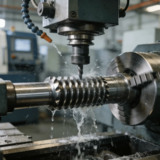
Splined shafts are cut by hobbing, broaching, shaping, milling, scudding (power skiving), cold rolling, grinding, wire EDM, or on a Swiss turn-mill, and the right choice follows four questions: internal or external, how many parts, what accuracy class, and how hard is the steel. There’s no single “best” method; the trade-off is what the 9-Process Spline-Cutting Method Map below is for.
| Method | Internal / External | Best volume | Accuracy | Cuts hardened? |
|---|---|---|---|---|
| Hobbing | External only | Medium–high | High | No (soft) |
| Linear broaching | Internal & external | High | High | Hard broaching: yes |
| Rotary broaching | Internal & external | Low–medium | Medium–high | Soft |
| Shaping | Internal (and external) | Low–medium | Medium | No |
| CNC milling | Internal & external | Prototype–low | High (5-axis) | No |
| Scudding / power skiving | Internal & external | Medium–high | High | Hard-finish capable |
| Cold rolling / forming | External only | Very high | Medium–high | No (formed soft) |
| Profile grinding | External (internal w/ small bore limit) | Any (finishing) | Highest | Yes (after HT) |
| Wire EDM | Internal & external | One-off–low | High | Yes (any hardness) |
Process capabilities per Gear Solutions and Gear Technology spline/gear cutting sources.
A few rules of thumb fall out of this map. Hobbing is the bread-and-butter method for external splines at volume because a hob, a rotary milling cutter, generates the involute form quickly with an excellent finish, but it can’t cut internal splines. Broaching uses a multi-tooth cutting tool pushed through in a single pass, and matching that tool to the part configuration is the whole game. Broaching owns internal splines and is among the fastest ways to fabricate one, as one machinist put it on an industry forum, “broaching is the fastest way to fabricate a spline” — though at high volume cold rolling and scudding compete. A counter-intuitive point that trips up buyers: broaching isn’t just a roughing process. Per Gear Solutions, hard broaching is applied specifically to internal splines that need precise concentricity. And scudding (power skiving) — a newer generating method, can cut internal and external splines and hard-finish them; its developer reports speeds up to five to six times faster than shaping for internal gears, per Gear Technology.
“Hard broaching is applicable for components that require precise concentricity, for example, internal splines.”
— Gear Solutions, “An Update on Broaching Technology”
You broach it, rotary-broach it in the lathe, or index it manually. For more than a few parts, the shop answer is to have a broach made and press it through on a mill or arbor press, or fit a rotary broach in the lathe turret.
A machinist on r/Machinists summarized the call this way: “Get a broach made and press it on the mill, or a rotary broach and cut it in the lathe, that’s how I’d do it if I need more than a few.” For one or two parts without any indexing, a dividing head or rotary table on the mill, a shaper with direct indexing, or even a lathe tool mounted on its side and racked back and forth will produce a usable spline. For internal splines in hardened parts where no cutter will survive, wire EDM cuts any hardness, it just takes longer. Lecreator runs CNC milling, turning, Swiss-type, wire EDM, and multitask turn-mill machining in-house, so the cutting method follows the part rather than the equipment at hand.
Spline accuracy is set by three things on the drawing: the governing standard, the tolerance class, and the fit class, together they bound the space width, tooth thickness, and form so the shaft and hub assemble and share load. One mistake to avoid is treating ANSI B92.1, ISO 4156, and DIN 5480 as interchangeable. They are not. Each has a defined scope, and citing the wrong one is the fastest way to lose an experienced reviewer’s trust.
| Standard | System / units | Pressure angles | Tolerance / fit classes |
|---|---|---|---|
| ANSI/ASME B92.1 | Inch, diametral pitch | 30°, 37.5°, 45° | Classes by space-width/tooth-thickness; side-fit focus |
| ANSI B92.2M | Metric module | 30°, 37.5°, 45° | Aligns with ISO 4156 basis |
| ISO 4156-1/2/3:2021 | Metric module, side-fit | 30°, 37.5°, 45° | Tolerance classes 4, 5, 6, 7; fit by deviation (H/d, H/e, H/f, H/h) |
| DIN 5480 | Metric, reference diameter | 30° only | Tolerance classes 5–12 (lower = tighter) |
| JIS D 2001 | Metric (Japanese auto) | 30° | Involute spline series for vehicles |
Class data per the ISO 4156-1:2021 standard and a tolerance analysis published by IAENG (WCE 2011); DIN range per DIN 5480-2 (current edition 2025).
Read the scope before you read the class. ISO 4156 covers straight (non-helical) side-fitting cylindrical involute splines, it is not a universal authority for every spline geometry, and it splits into part 1 (design), part 2 (dimensions), and part 3 (inspection). DIN 5480 is limited to a 30° pressure angle because the 37.5° and 45° angles are handled by ISO 4156. In ISO 4156, the internal spline tolerance position is always “H,” and the fit is set by the external (shaft) deviation. Tolerance class 4 is the tightest and 7 the loosest; DIN 5480 runs 5 through 12 on the same principle. For a sliding spline you specify a looser fit so it moves freely; for a fixed, concentric joint you tighten it. A real spline callout therefore looks like “Involute, 30° PA, 24/48 diametral pitch, ISO 4156 class 5, side-fit H/f” — not just “spline.” This is the kind of tight-tolerance work where the standard, not the shop, defines acceptance.
Concentricity in a splined shaft means the spline pitch circle stays on the same axis as the bearing journals, so the part runs without the wobble that drive vibration, noise, and uneven tooth wear. You control it two ways: by choosing how the spline centers on its mating hub, and by minimizing how many times the part is re-fixtured while it’s cut. Both matter, and the second is where most runout actually comes from.
The centering method is a design decision with real consequences. The side (flank) fit that ISO 4156 and ANSI B92.1 standardize locates on the tooth flanks and is the default for torque transmission; a major-diameter fit instead locates on the tooth tips and is chosen specifically when concentricity is the priority; minor-diameter fit is the third option. One caveat worth stating: the side-fit standards (ISO 4156, ANSI B92.1) do not fully cover major-diameter-fit tolerancing, SAE notes the ANSI B92.1/96 addendum does not apply to major-diameter-fit splines, so a major-diameter fit is a deliberate engineering choice that needs its own tolerance treatment, not a clause you can copy from the side-fit table.
| Centering method | Locates on | Best for |
|---|---|---|
| Side (flank) fit | Tooth flanks | Torque transmission (the default standard) |
| Major-diameter fit | Tooth tips (OD) | Best concentricity; measurable over pins |
| Minor-diameter fit | Root / minor diameter | Alternative centering; harder to gauge over pins |
Every time a shaft is unclamped and re-fixtured between operations, the new setup adds its own error to the total indicated runout (TIR) between the spline and the journals. A shaft turned, then moved to a separate hobber, then to a grinder, stacks three setup errors. Cutting the journals and generating the spline in one clamping on a multitask (turn-mill) machine or Swiss lathe collapses that stack to one reference, which is the single most effective way to hold tight TIR. Lecreator routes concentricity-critical splined shafts through single-setup turn-mill or Swiss machining for exactly this reason.

Material selection for a splined shaft balances core toughness, surface wear resistance, and machinability, and the heat-treat route usually matters more than the base alloy. The dominant choice is a case-hardening steel cut soft, then carburized to a hard wear surface over a tough core, because a spline need a hard flank that resists wear but a core ductile enough to absorb shock loads.
| Material | Heat-treat route | Typical hardness | Spline use |
|---|---|---|---|
| 8620 | Carburize (case harden) | 58–62 HRC case | Workhorse gear/spline blank |
| 9310 | Carburize | 58–62 HRC case | Aerospace, high-load |
| 4140 | Through-harden / pre-hard | 28–32 HRC | General duty, machine soft |
| 4340 | Through-harden + temper | 32–40 HRC | High strength shafts |
| 4150 / 4145 | Induction harden splines | 50–58 HRC zone | Axle / drive shafts |
| 1045 | Induction or as-rolled | 45–55 HRC zone | Cost-driven carbon steel parts |
| 5120 / 20MnCr5 | Carburize | 58–62 HRC case | European auto splines |
| 17-4 PH stainless | Precipitation harden (H900) | ~40–44 HRC | Corrosion + strength |
| Nitriding alloy (Nitralloy) | Nitride (low distortion) | 60–65 HRC surface | Distortion-critical splines |
Hardness ranges synthesized from AISI 8620 datasheets and gear heat-treat references; verify against your supplier’s certified mill data.
Heat treatment gives the spline its wear life, but it also distorts the part, which is why the sequence is usually cut soft, harden, then finish. The distortion is real and varies with process and geometry, so treat published numbers as examples, not a universal rule.
Gear Solutions reports that in induction hardening the last tooth can be pushed out 0.1 to 0.8 mm, while a peer-reviewed study of an 8620H gear (published via DOAJ) measured end-face runout near 0.023 mm before heat treat and 0.059 mm after. Typical carburized case depth runs 0.3 to 0.5 mm with a core above 25 HRC; the hardened case surface depends on the steel and spec, carburized 8620 commonly finishes around 58–62 HRC, with some gear flanks specified higher. A shop running spline blanks day in and day out put it plainly on an industry forum: “mainly it’s 8620 at 58/62 Rc with a .06 case; for through-hard work, 4140 pre-hard at 28/32.” When the case-hardened spline has to hold a tight class after that distortion, you finish-grind the flanks, which is the only method on the map that cuts a fully hardened part to the highest accuracy. For corrosion plus strength, 17-4 PH stainless is the usual answer; see our notes on 17-4 PH machining.

The fit between a splined shaft and its hub decides whether the joint slides, locks, or rattles, and you set it deliberately with a clearance, transition, or interference class plus a backlash target. A sliding spline (a shift collar, a PTO) needs clearance so it moves under load; a fixed coupling need little or no backlash so it doesn’t hammer itself loose. Backlash is the rotational free play between the mating teeth, and it trades off against assembly ease: too tight and the parts gall on assembly, too loose and the joint pounds under reversing torque.
Practically, match the fit class to the job: a free-sliding spline uses a loose class (for example ISO 4156 H/e or H/d), a close-sliding spline a mid class (H/f), and a located, non-sliding joint the tightest class your process holds. If the hub is a separate gear or coupling, the same logic applies, and a splined connection still carries far more torque than a single key for the same diameter, which is the whole reason to use one. This is a frequent decision point in choosing between turning versus milling a given feature.
Spline inspection verifies that the as-cut teeth fall inside the standard’s tolerance class, and it uses three layers: composite GO gauges, element NO-GO gauges, and dimensional measurement over pins or by CMM. ISO 4156-3 defines the inspection scope for side-fitting involute splines, so the gauging is not just shop preference, it is part of the standard you cited on the drawing.
| Method | What it checks | When to use |
|---|---|---|
| Composite GO gauge | Effective fit over all teeth (will it assemble) | Production go/no-go |
| Element NO-GO gauge | Actual tooth thickness / space width limit | Confirm not too loose |
| Measurement over pins/balls | Tooth thickness via two pins in opposing spaces | First-article, major-dia fit |
| CMM scan | Profile, index, lead, runout to journals | Tight-class / aerospace parts |
The practical workflow is to gauge every part with the composite and element gauges for assembly, then prove the dimension on a first article with measurement over pins and a CMM. Note one limit from the standards: a minor-diameter-fit shaft’s double spaces can’t be measured over pins, so plan the CMM route for those. Lecreator documents this with first-article inspection and a CMM report on every order; our notes on CMM inspection and first article inspection cover the paperwork. On the shop floor, machinists confirm an interference fit between a splined shaft and hub by taking a CMM measurement or shadowgraph as the master to compare against.
The cost of a splined shaft is driven less by the spline itself than by the accuracy class, the heat-treat-and-grind sequence, and the volume, and most of it’s controllable at the design stage. A spline ground after carburizing to a class-5 fit can cost several times a soft-cut class-7 spline of the same size. The biggest lever is to specify only the accuracy the application need.
For buyers sourcing offshore, total landed cost matters as much as the piece price. Lecreator quotes splined shafts on transparent DDP terms with duties included and ships from China with first-article and material-traceability documentation, so the cost on the quote is the cost at your dock. The turning and CNC machining capability behind that’s the same line that runs the concentricity-critical work above.
Demand for precision splined shafts tracks the drivetrain market, and the near-term shifts are electrification, lightweighting, and net-shape forming. The global spline shaft market sits around USD 1.7–1.85 billion with a mid-single-digit growth rate, and the automotive drive shaft market it feeds is forecast in the same 4.9–5.6% CAGR band through the early 2030s (market-research estimates, directional, not audited).
Three engineering trends are worth planning around now. First, EV halfshafts and e-axle couplings lean on splined and face-spline connections, face splines on driven wheel hubs are already a granted patent area (US 8,444,322 B2). Second, near-net cold forming and rolling of spline teeth (US 5,213,250 A) improves material use and fatigue strength versus cutting, which matters as volumes climb. Third, generating methods like scudding and power skiving, and even additive-manufactured strain-wave flexsplines (WO 2018/165662 A1), are widening what counts as a “machined” spline. The action item for a buyer: when you start a new program, ask your shop which of these process chains fits your volume, the cheapest spline at 100 parts is rarely the cheapest at 100,000.
Updated June 2026.
This guide pairs the published spline standards (ANSI B92.1, ISO 4156, DIN 5480) and peer-reviewed and trade research on broaching, heat-treat distortion, and centering with our own shop practice machining splined shafts and rotating parts. The concentricity, inspection, and single-setup points reflect how we route concentricity-critical work through turn-mill and Swiss machining with CMM verification. Reviewed by the Shenzhen Le-creator Technology Co., Ltd. technical team.
Need splined shafts cut to a specific standard and fit class, with first-article and material documentation?