Service de soutien, professionnel et axé sur le client
Entrez en contact avec Lecreator Company
Des prototypes à la production à grande échelle, nous avons ce qu'il vous faut.


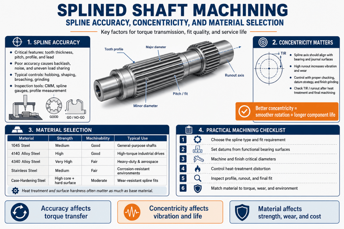
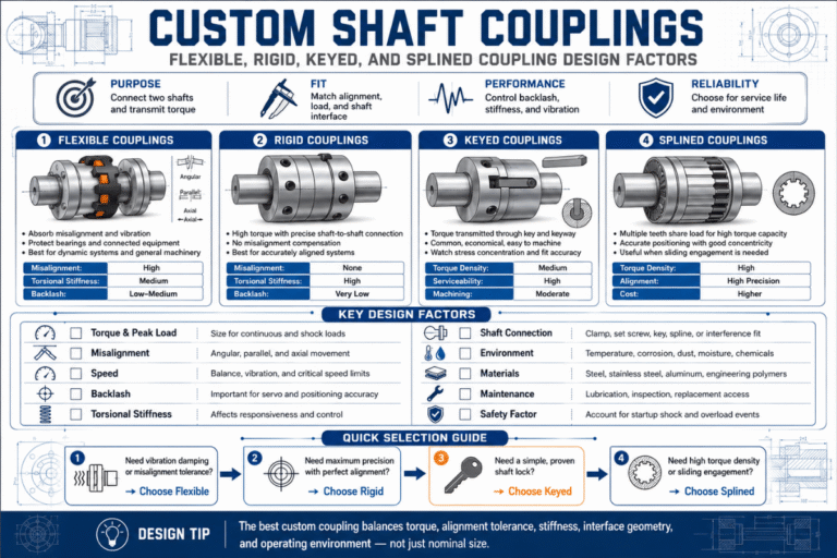
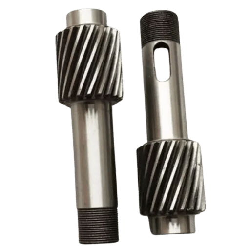
L'usinage à arbre fendu est le processus de coupe d'une série de dents, de crêtes ou de rainures le long d'un arbre afin qu'il puisse transmettre le couple à un moyeu correspondant tout en maintenant l'alignement, et les trois choses qui décident si la pièce fonctionne sont la précision de la cannelure, la concentricité et la sélection du matériau. Obtenez la bonne classe d'ajustement, maintenez la cannelure fidèle aux tourillons de roulement et choisissez un acier et un traitement thermique qui survivent à la charge, et un arbre cannelé dépasse l'assemblage autour de lui. Mademoiselle un, et vous obtenez un jeu, un fretting ou une pièce qui ne s'assemblera pas. Ce guide passe par les méthodes, les normes et les décisions qu'un usiniste en activité ou un acheteur doit réellement prendre.
| Normes régissant | ANSI/ASME B92.1 (pouce) · ANSI B92.2M /ISO 4156-1/2/3 :2021 (métrique, side-fit) · DIN 5480 (diamètre de référence) · JIS D 2001 |
| Formes splines | Involute · recto (parallèle) · dentelé · hélicoïdal · couronné · boule |
| Centrage/ajustement | Coupe latérale (flanc), coupe de diamètre majeur, coupe de diamètre mineur |
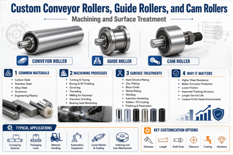
| Matériaux communs | 8620, 4140, 4340, 1045, inoxydable 17-4 PH |
| Méthodes de découpe | Hobbing, brochage, façonnage, fraisage, écudage/patinage électrique, laminage à froid, meulage, EDM filaire |
| Inspection | Jauges composites GO /élément NO-GO, mesure sur broches, CMM (selon ISO 4156-3) |
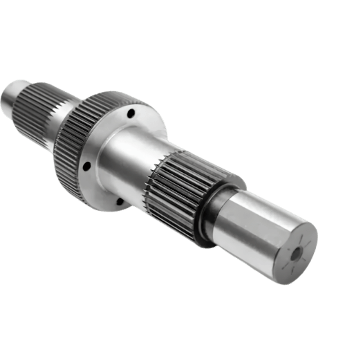
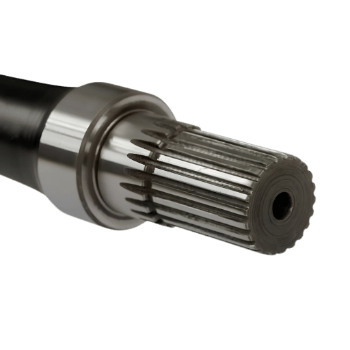
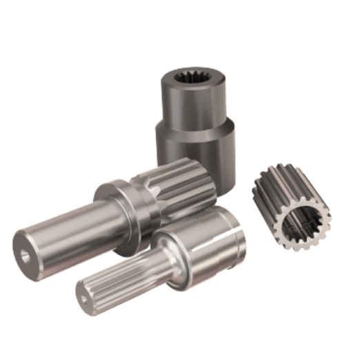
Un arbre cannelé est un arbre cylindrique avec plusieurs dents (les cannelures) coupées parallèlement à son axe qui engrènent avec des rainures correspondantes dans une pièce correspondante, un engrenage, un moyeu ou un accouplement, pour transmettre le couple et maintenir les deux pièces alignées. Contrairement à une seule clé dans une rainure de clavette, les cannelures répartissent la charge sur de nombreuses dents, de sorte que le même diamètre d'arbre transporte beaucoup plus de couple, fonctionne avec moins de concentration de contraintes et peut laisser le moyeu glisser axialement tout en l'entraînant.
Cette capacité de glissement est la raison pour laquelle arbres d'entraînement, 1, les mécanismes de changement de vitesse de transmission et les colonnes de direction pliables utilisent des cannelures plutôt que des touches.
Réglez d'abord la forme spline, car elle entraîne la méthode de coupe, la norme et le coût. Le tableau ci-dessous regroupe les formulaires qu'il vous sera réellement demandé de créer.
| Forme spline | Profil dentaire | Norme applicable | Utilisation typique |
|---|---|---|---|
| Involuté (30°) | Flancs de développante courbés, autocentrants | ANSI B92.1/ISO 4156/DIN 5480 | Transmissions automatiques, boîtes de vitesses |
| Involuté (37,5°) | Angle de pression plus élevé, racine plus forte | ANSI B92.1/ISO 4156 | Des cannelures compactes à couple élevé |
| Involuté (45°) | Peu profond, beaucoup de dents | ANSI B92.1 (racine de filet) | Pas fin, petits diamètres |
| Droite (parallèle) | Flancs plats et parallèles | SAE /ISO 14 (plus âgé) | PTO agricole, entraînements à basse vitesse |
| Serré | Dents en forme de V à 45°/60° | SAE J498 | Poignets de réglage, positionnement par ajustement serré |
| Involute helique | Dents en développante coudée | ISO 4156 (annexe hélicoïdale) | Transfert de couple fluide à grande vitesse |
| Couronné | Flanc en tonneau sur toute la longueur | Par dessin/OEM | Accouplements tolérants au désalignement |
| Flèche de balle | Rainures à billes à recirculation | Spécifique au fabricant | Robotique linéaire plus couple à faible friction |
| Flèche du visage (Hirth) | Dents radiales sur une face d'extrémité | Par dessin/DIN 5481-adjacent | Moyeux de roues, accouplements d'indexation |
Formulaires compilés à partir des définitions de géométrie spline ANSI B92.1 et ISO 4156.
Les cannelures invariantes dominent car les flancs incurvés sont autocentrés et partagent la charge en douceur, c'est pourquoi presque toutes les arbre tourné de précision dans une boîte de vitesses moderne les utilise Les cannelures droites apparaissent toujours sur les arbres de prise de force agricoles où la simplicité bat l'efficacité. Note d'ingénierie: si votre impression indique simplement “spline,” demande quelle norme et quelle coupe avant de citer, le formulaire à lui seul ne détermine pas l'épaisseur de la dent ni la méthode d'inspection.
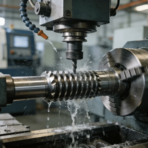
Les arbres fendus sont coupés par taillage, brochage, façonnage, fraisage, écudage (patinage électrique), laminage à froid, meulage, EDM filaire ou sur un laminoir suisse, et le bon choix suit quatre questions : interne ou externe, combien de pièces, quelle classe de précision et quelle est la dureté de l'acier. Il n'existe pas de méthode unique de “best” ; le compromis est ce que le Carte de la méthode de découpe Spline 9-Process ci-dessous est pour.
| Méthode | Interne /Externe | Meilleur volume | Précision | Des coupes durcies? |
|---|---|---|---|---|
| Hobb | Externe seulement | Moyen | Haut | Non (doux) |
| Brochage linéaire | Interne & externe | Haut | Haut | Brochage dur : oui |
| Brochage rotatif | Interne & externe | Bas | Moyen | Doux |
| Façonner | Interne (et externe) | Bas | Moyen | Non |
| Fraisage CNC | Interne & externe | Prototype | Élevé (5 axes) | Non |
| Scudding/patinage électrique | Interne & externe | Moyen | Haut | Capable de finition dure |
| Laminage à froid/formage | Externe seulement | Très haut | Moyen | Non (formé doux) |
| Rectification de profilés | Externe (interne w/limite de petit alésage) | N'importe lequel (finition) | Plus haut | Oui (après HT) |
| ÉDM filaire | Interne & externe | Un seul coup | Haut | Oui (toute dureté) |
Capacités de processus par solutions d'engrenages et sources de coupe cannelées/engrenages Gear Technology.
Quelques règles empiriques tombent de cette carte Le hobbing est la méthode du pain et du beurre pour les cannelures externes au volume car une plaque de cuisson, un fraiseur rotatif, génère rapidement la forme en développante avec une excellente finition, mais il ne peut pas couper les cannelures internes Le brochage utilise un outil de coupe à plusieurs dents poussé en un seul passage, et faire correspondre cet outil à la configuration de la pièce est tout le jeu Le brochage possède des cannelures internes et est parmi les moyens les plus rapides d'en fabriquer une, comme l'a dit un machiniste sur un forum de l'industrie, le brochage est le moyen le plus rapide de fabriquer une cannelure à froid à grand volume et le scudding rivalisent Un point contre-intuitif trébuche les acheteurs : le brochage n'est pas qu'un processus de rugosité Per Solutions d'engrenages, ., le brochage dur est appliqué spécifiquement aux cannelures internes qui nécessitent une concentricité précise. Et le scudding (power skiving) (une méthode de génération plus récente), peut couper les cannelures internes et externes et les terminer dur ; ses rapports de développeur accélèrent jusqu'à cinq à six fois plus vite que la mise en forme des engrenages internes, par Technologie d'engrenage.
“Le brochage”Hard est applicable pour les composants qui nécessitent une concentricité précise, par exemple, les cannelures internes.”
“An Update on Broaching Technology”
Vous le brochez, le brochez rotatif dans le tour ou l'indexez manuellement. Pour plus de quelques pièces, la réponse du magasin est de faire fabriquer une broche et de la presser sur un moulin ou une presse à tonnelle, ou d'installer une broche rotative dans la tourelle du tour.
Un machiniste sur r/Machinistes résumait l'appel ainsi : “Faites fabriquer une broche et appuyez-la sur le moulin, ou une broche rotative et coupez-la dans le tour, c'est comme ça que je le ferais si j'en avais besoin de plus de quelques-uns.” Pour une ou deux pièces sans aucune indexation, une tête de séparation ou table rotative sur le moulin, un conformateur à indexation directe, ou encore un outil de tour monté sur le côté et rayé d'avant en arrière produira une cannelure utilisable Pour les cannelures internes en pièces durcies où aucune fraise ne survivra, câble EDM coupe n'importe quelle dureté, cela prend juste plus de temps Lecreator fonctionne Fraisage CNC, « Tournage, type suisse, EDM filaire et usinage multitâche au laminoir en interne, de sorte que la méthode de coupe suit la pièce plutôt que l'équipement disponible ».
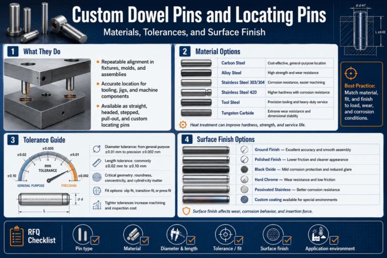
La précision de la cannelure est définie par trois choses sur le dessin : la norme régissant, la classe de tolérance et la classe d'ajustement, ensemble, ils délimitent la largeur de l'espace, l'épaisseur de la dent et forment de sorte que l'arbre et le moyeu s'assemblent et partagent la charge. Une erreur à éviter est de traiter ANSI B92.1, ISO 4156 et DIN 5480 comme interchangeables. Ils ne le sont pas. Chacun a une portée définie, et citer le mauvais est le moyen le plus rapide de perdre la confiance d'un évaluateur expérimenté.
| Standard | Système /unités | Angles de pression | Tolérance/classes d'ajustement |
|---|---|---|---|
| ANSI/ASME B92.1 | Pouce, pas diamétral | 30°, 37.5°, 45° | Classes par largeur d'espace/épaisseur des dents ; mise au point latérale |
| ANSI B92.2M | Module métrique | 30°, 37.5°, 45° | S'aligne sur la base ISO 4156 |
| ISO 4156-1/2/3:2021 | Module métrique, side-fit | 30°, 37.5°, 45° | Classes de tolérance 4, 5, 6, 7 ; ajustement par déviation (H/d, H/e, H/f, H/h) |
| DIN 5480 | Métrique, diamètre de référence | 30° seulement | Classes de tolérance 512 (inférieure = plus serrée) |
| JIS D 2001 | Métrique (automobile japonaise) | 30° | Série spline absolue pour véhicules |
Données de classe par ISO 4156-1:2021 norme et une analyse de tolérance publiée par IAENG (WCE 2011); Gamme DIN par DIN 5480-2 (édition actuelle 2025).
Lisez la portée avant de lire le cours. ISO 4156 couvre droit (non hélicoïdal) ajustement latéral cannelures cylindriques à développante, ce n'est pas une autorité universelle pour chaque géométrie de cannelure, et elle se divise en partie 1 (conception), partie 2 (dimensions) et partie 3 (inspection).DIN 5480 est limitée à un angle de pression de 30° car les angles de 37,5° et 45° sont gérés par ISO 4156. Dans ISO 4156, la position de tolérance de cannelure interne est toujours 1H, le“ et l'ajustement est défini par la déviation externe (arbre) classe de tolérance 4 est la plus serrée et 7 le plus lâche ; DIN 5440 passe librement par la même ligne de serrage, vous indique 5, vous est un modèle fixe.
La concentricité dans un arbre cannelé signifie que le cercle primitif cannelé reste sur le même axe que les tourillons de roulement, de sorte que la pièce fonctionne sans l'oscillation qui entraîne les vibrations, le bruit et l'usure inégale des dents. Vous le contrôlez de deux manières : en choisissant la façon dont la cannelure se concentre sur son moyeu d'accouplement et en minimisant le nombre de fois où la pièce est refixée pendant sa coupe. Les deux comptent, et la seconde est d'où vient réellement la plupart des faux-rond.
La méthode de centrage est une décision de conception avec des conséquences réelles. L'ajustement latéral (flanc) que les normes ISO 4156 et ANSI B92.1 localisent sur les flancs des dents et constitue la valeur par défaut pour la transmission du couple ; un ajustement de diamètre majeur se situe plutôt sur les pointes des dents et est choisi spécifiquement lorsque la concentricité est la priorité ; l'ajustement de diamètre mineur est la troisième option. Une mise en garde mérite d'être formulée : les normes d'ajustement latéral (ISO 4156, ANSI B92.1) ne couvrent pas entièrement la tolérance d'ajustement majeur, SAE note que l'addendum ANSI B92.1/96 ne s'adapte pas à un choix délibéré de spdiam de traitement.
| Méthode de centrage | Se situe sur | Meilleur pour |
|---|---|---|
| Coupe latérale (flanc) | Flancs dentaires | Transmission de couple (la norme par défaut) |
| Ajustement majeur-diamètre | Embouts dentaires (OD) | Meilleure concentricité ; mesurable sur des broches |
| Ajustement de diamètre mineur | Racine/diamètre mineur | Centrement alternatif ; plus difficile à évaluer sur les broches |
Chaque fois qu'un arbre est desserré et refixé entre les opérations, la nouvelle configuration ajoute sa propre erreur au faux-rond total indiqué (TIR) entre la cannelure et les tourillons Un arbre tourné, puis déplacé vers un hobber séparé, puis vers un broyeur, empile trois erreurs de configuration Couper les tourillons et générer la cannelure en un seul serrage sur un machine multitâche (à moulinet) ou Tour suisse réduit cette pile à une seule référence, ce qui est le moyen le plus efficace de maintenir un TIR serré. Lecreator achemine les arbres cannelés critiques pour la concentricité via un laminoir à un seul réglage ou un usinage suisse pour exactement cette raison.

La sélection des matériaux pour un arbre cannelé équilibre la ténacité du noyau, la résistance à l'usure de la surface et l'usinabilité, et la voie de traitement thermique compte généralement plus que l'alliage de base. Le choix dominant est un acier cémenté coupé doux, puis carburé sur une surface d'usure dure sur un noyau résistant, car une cannelure a besoin d'un flanc dur qui résiste à l'usure mais d'un noyau suffisamment ductile pour absorber les charges de choc.
| Matériel | Voie de traitement thermique | Dureté typique | Utilisation de spline |
|---|---|---|---|
| 8620 | Carburer (durcir le boîtier) | 586 2 Affaire HRC | Equive d'engrenage/de cannelure d'hippocampe |
| 9310 | Carburer | 586 2 Affaire HRC | Aérospatiale, à charge élevée |
| 4140 | Durcissant/pré-dur | 283HRC | Service général, machine douce |
| 4340 | Durci + tempérament | 320 HRC | Arbres à haute résistance |
| 4150 / 4145 | Induction durcir les cannelures | 500 zone HRC | Essieu/arbres d'entraînement |
| 1045 | Induction ou laminé | 455 zone HRC | Pièces en acier au carbone à coût |
| 5120 /20MnCr5 | Carburer | 586 2 Affaire HRC | Des cannelures automobiles européennes |
| inoxydable 17-4 PH | Durcissement des précipitations (H900) | ~404 HRC | Corrosion + force |
| Alliage nitrurant (Nitralloy) | Nitrure (faible distorsion) | 60 60 HRC surface | Splines critiques pour la distorsion |
Plages de dureté synthétisées à partir des fiches techniques AISI 8620 et des références de traitement thermique des engrenages ; vérifiez par rapport aux données certifiées de l'usine de votre fournisseur.
Le traitement thermique donne à la cannelure sa durée de vie, mais il déforme également la pièce, c'est pourquoi la séquence est généralement coupée mollement, durcie, puis terminée La distorsion est réelle et varie avec le processus et la géométrie, alors traitez les nombres publiés comme des exemples, pas comme une règle universelle.
Solutions d'engrenages rapporte qu'en durcissant par induction, la dernière dent peut être poussée de 0,1 à 0,8 mm, tandis qu'une étude évaluée par des pairs sur un engrenage de 8 620 H (publié via DOAJ) épuisement mesuré près de 0,023 mm avant traitement thermique et 0,059 mm après. La profondeur typique du boîtier carburé est de 0,3 à 0,5 mm avec un noyau supérieur à 25 HRC ; la surface du boîtier durci dépend de l'acier et des spécifications, le 862 carburé se termine généralement autour de 58 coupes 6 HRC, avec quelques flancs de boîte spécifiés plus haut. Un atelier exécutant des ébauches de cannelure jour après jour le pose clairement sur un forum industriel : principalement, c'est serré 8620 à 58/62 Rc avec une réponse 06 durci que la méthode de corrosion 1 durci, maintende 40. Usinage 17-4 PH.

L'ajustement entre un arbre cannelé et son moyeu décide si l'articulation glisse, se verrouille ou s'agite, et vous la réglez délibérément avec une classe de dégagement, de transition ou d'interférence plus une cible de jeu. Une cannelure coulissante (un collier de changement de vitesse, une prise de force) a besoin d'un dégagement pour se déplacer sous charge ; un accouplement fixe n'a besoin que de peu ou pas de jeu pour ne pas se détacher. Le jeu arrière est le jeu libre de rotation entre les dents qui s'accouplent, et il se heurte à la facilité d'assemblage : trop serré et les pièces galbent lors de l'assemblage, trop lâches et le joint sous couple d'inversion.
Pratiquement, faites correspondre la classe d'ajustement au travail : une cannelure coulissante libre utilise une classe lâche (par exemple ISO 4156 H/e ou H/d), une cannelure coulissante rapprochée une classe moyenne (H/f) et une articulation localisée, non coulissante, la classe la plus serrée que votre processus détient Si le moyeu est un engrenage ou un accouplement séparé, la même logique s'applique, et une connexion cannelée transporte toujours beaucoup plus de couple qu'une seule clé pour le même diamètre, ce qui est la raison complète d'en utiliser une. C'est un point de décision fréquent dans le choix entre tourner et fraiser une caractéristique donnée.
L'inspection des cannelures vérifie que les dents telles que coupées se situent à l'intérieur de la classe de tolérance de la norme, et elle utilise trois couches : les jauges GO composites, les jauges NO-GO d'éléments et la mesure dimensionnelle sur des broches ou par CMM. L'ISO 4156-3 définit la portée d'inspection pour les cannelures à développante latérales, de sorte que le jaugeage n'est pas seulement une préférence d'atelier, il fait partie de la norme que vous avez citée sur le dessin.
| Méthode | Ce qu'il vérifie | Quand utiliser |
|---|---|---|
| Jauge GO composite | Ajustement efficace sur toutes les dents (sera-t-il assemblé) | Production go/no-go |
| Jauge élément NO-GO | Épaisseur réelle de la dent/limite de largeur d'espace | Confirmez que ce n'est pas trop lâche |
| Mesure sur des quilles/billes | Épaisseur de dents via deux broches dans des espaces opposés | Premier article, ajustement majeur |
| Analyse CMM | Profil, index, lead, runout aux revues | Pièces de classe serrée/aérospatiale |
Le workflow pratique consiste à jauger chaque pièce avec les jauges composite et élément pour l'assemblage, puis à prouver la dimension sur un premier article avec mesure sur broches et un CMM. Notez une limite des normes : les doubles espaces d'un arbre à petit diamètre ne peuvent pas être mesurés sur broches, alors planifiez l'itinéraire CMM pour celles-ci. Lecreator documente cela avec une inspection du premier article et un rapport CMM sur chaque commande ; nos notes sur Inspection CMM et inspection du premier article couvrir les documents Sur le sol de l'atelier, les machinistes confirment un ajustement serré entre un arbre cannelé et le moyeu en prenant une mesure CMM ou un graphique d'ombre comme maître à comparer.
Le coût d'un arbre cannelé est moins entraîné par la cannelure elle-même que par la classe de précision, la séquence de traitement thermique et de meulage et le volume, et la majeure partie est contrôlable au stade de la conception. Une cannelure au sol après avoir carburé jusqu'à un ajustement de classe 5 peut coûter plusieurs fois une cannelure de classe 7 à coupe souple de même taille. Le plus gros levier est de spécifier uniquement la précision dont l’application a besoin.
Pour les acheteurs s'approvisionnant en mer, le coût total au débarquement compte autant que le prix à la pièce Lecreator cite les puits cannelés selon des conditions DDP transparentes avec les droits inclus et les navires en provenance de Chine avec la documentation du premier article et de la traçabilité des matériaux, donc le coût sur le devis est le coût à votre quai. Le tournage et Usinage CNC la capacité derrière c'est la même ligne qui exécute le travail critique en termes de concentricité ci-dessus.
La demande d'arbres cannelés de précision suit le marché des transmissions, et les changements à court terme sont l'électrification, l'allègement et la formation de la forme du filet. Le marché mondial des arbres cannelés se situe autour de 1,75 milliard de dollars avec un taux de croissance à un chiffre moyen, et le marché des arbres de transmission automobiles qu'il alimente est prévu dans la même bande CAGR de 4,95,61TP3 jusqu'au début des années 2030 (estimations de recherche de marché, directionnelles, non auditées).
Trois tendances techniques méritent d'être planifiées à l'heure actuelle. Premièrement, les demi-arbres EV et les accouplements à essieu électronique s'appuient sur des connexions cannelées et à cannelure frontale, les cannelures frontales sur les moyeux de roues motrices constituent déjà un domaine de brevet accordé (8 444 322 B2). Deuxièmement, le formage à froid quasi net et le laminage des dents cannelées (5 213 250 A) améliore l'utilisation des matériaux et la résistance à la fatigue par rapport à la coupe, ce qui est important à mesure que les volumes augmentent. Troisièmement, des méthodes de génération comme le scudding et le patinage électrique, et même des lignes flexibles à ondes de déformation fabriquées de manière additive (splines flexibles à ondes de déformation)WO 2018/165662A1), élargissent ce qui compte comme une cannelure de“ usinée d”“ L'élément d'action pour un acheteur : lorsque vous démarrez un nouveau programme, demandez à votre boutique laquelle de ces chaînes de processus correspond à votre volume, la cannelure la moins chère à 100 parties est rarement la moins chère à 100 000.
Mis à jour en juin 2026.
Ce guide associe les normes de cannelure publiées (ANSI B92.1, ISO 4156, DIN 5480) et la recherche évaluée par des pairs et commerciale sur le brochage, la distorsion de traitement thermique et le centrage avec notre propre pratique d'atelier d'usinage d'arbres cannelés et de pièces rotatives. La concentricité, l'inspection et les points de réglage uniques reflètent la façon dont nous acheminons le travail critique en matière de concentricité à travers un laminoir et un usinage suisse avec vérification CMM. Examiné par l'équipe technique de Shenzhen Le-creator Technology Co., Ltd.
Besoin de tiges cannelées coupées à une classe standard et d'ajustement spécifique, avec documentation sur le premier article et le matériel ?