

Supportive, Professional, Client-Focused Service
From prototypes to full-scale production, we’ve got you covered.


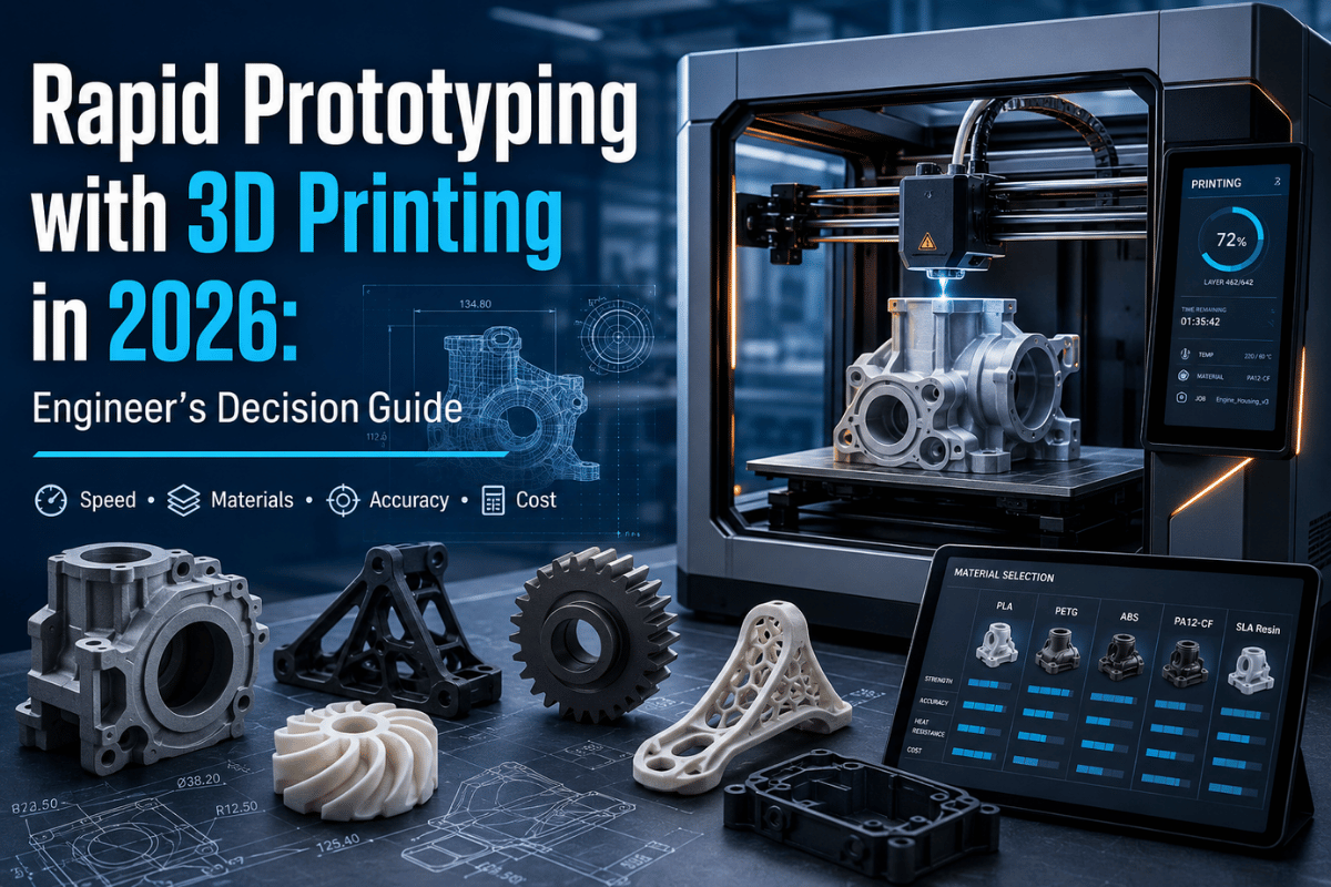
rapid prototyping with 3d printing is the tactical workflow the majority of engineering groups use now to get a computer-aided design (CAD) model into a physical part in 4 hours to 5 days a matter of a decision-driven rapid prototyping process that seizes one of six 3d printing technologies, validates the design against tolerance and material limits, and (for parts over 50 units) compares the per-unit landed cost from a U.S. shop versus a China-DDP option bearing Section 301 tariffs. The purpose of the iterative process is to shorten product development iterations and get products into traditional methods than market faster. This cheat sheet dissects the six technologies, the eight design principles engineers most often forget, and the actual $7,425 landed cost of a 50-unit shipment so you can select the correct path before you spend a week on iteration.
| Tolerance range (best to typical) | ±0.025 mm (DMLS) → ±0.5 mm (FDM) |
| Lead time (in-house desktop SLA → service-bureau metal) | 4 hours → 7 working days |
| Material families | Thermoplastics, photopolymer resin, nylon PA, elastomer, metal alloy, ceramic |
| Cost ratio (50-part run: China DDP vs U.S. shop) | $7,425 vs ~$14,500 (~49% lower with DDP) |
| Section 301 tariff (China-origin AM parts) | 25% on HTS 8466 / 8479 / 3926 / 9031 categories |
| Iteration cycle (rapid prototyping vs traditional tooling) | 1–3 days vs 6–8 weeks |

3d printing and rapid prototyping are no longer synonyms, but the terms were interchangeable for almost 20 years, and that history still confuses procurement discussions today. Rapid prototyping is the goal – producing a physical prototype fast enough that engineers can Risuk before user-test, and 3d printing is one of the tools that achieves that goal, and still the largest application of additive manufacturing in 2026. ISO/ASTM 52900:2021, the additive manufacturing standard of today, clarifies this by classifying 3d printing technologies (and its industry peer, additive manufacturing) as one of many types of printing process, not a use case.
No. 3d printing is a manufacturing process; rapid prototyping is how you use it. The two words were called interchangeable through out the 1990s because the first commercial machines – stereolithography in 1986 and selective laser sintering in 1989 – were used nearly solely for making prototype parts. The Markforged team comes right out and says: rapid prototyping is “mainly associated with the old era of 3d printers,” and most of the industry has progressed to additive manufacturing as an umbrella term once printers could make production-quality end use parts.
For an engineer running a product development cycle in 2026, the distinction matters in two places: first, when you pull SERP results – a search for “rapid prototyping” spits out service-bureau pages, while “additive manufacturing” spits out printer-OEM and standards content; and second, when you write a purchase order – writing “3d printed prototype” leaves the technology choice to your provider, while writing “SLS Nylon PA12 prototype to ISO/ASTM 52900” rrules in the process, material and dimensional expectations. The iterative loop lives at the center of this discussion: multiple iterations let your team validate ergonomics, fit and function before tooling is cut.
Form say ”send me a 3D-printed prototype’ and you are giving your manufacturer free rein to employ any idle additive process. great for a form-and-fit model, not so good for anything you need to functionally test. Engineers we work with through our rapid prototyping service who specify process, material, layer height, and orientation up front get prototypes that pass first-article inspection roughly four times more often than those who specify only ”3d printed.’

Six additive processes dominate rapid prototyping in 2026, and each one trades one parameter for another – tolerance for build volume, surface finish for strength, machine for cost per part. The table below, reproduced from the Protolabs design-tip, the Formlabs FDM-SLA-SLS buyer guide and the EOS / 3D Systems /HP Multi Jet Fusion datasheets, cross checked against shop floor measurements, is the comparison we ask buyers to start with before they go any deeper.
| Technology | Tolerance (typical) | Build volume (typical industrial) | Materials | Layer height | Lead time (50 pcs) | Best for |
|---|---|---|---|---|---|---|
| SLA (stereolithography) | ±0.1 mm or ±0.2% | 300 × 335 × 200 mm | Photopolymer resin (rigid, tough, castable, dental) | 25–100 µm | 2–4 days | Cosmetic prototypes, jewelry, dental, fine-detail concept models |
| SLS (selective laser sintering) | ±0.3 mm or ±0.3% | 340 × 340 × 600 mm | Nylon PA12, PA11, glass-filled nylon, TPU | 100–150 µm | 3–5 days | Functional plastic prototypes, snap-fits, low-volume production runs |
| MJF (multi jet fusion) | ±0.305 mm first inch + 0.1% | 380 × 285 × 380 mm | Nylon PA12, PA11, TPU, polypropylene | 80–120 µm | 3–5 days | Mid-volume functional production (50–1,000 pcs), isotropic strength |
| FDM / FFF (extrusion) | ±0.5 mm or ±0.5% | 600 × 600 × 600 mm (industrial) | PLA, ABS, PETG, ASA, PC, PEI/ULTEM, PEEK | 100–400 µm | 1–3 days | Concept models, large prototypes, jigs and fixtures, low-budget iterations |
| PolyJet (material jetting) | ±0.1 mm typical, multi-material | 490 × 390 × 200 mm | Vero rigid, Agilus30 elastomer, Digital ABS — 100+ digital blends | 14–30 µm | 2–4 days | Ultra-realistic visual prototypes, CMF validation, multi-material assemblies |
| DMLS / SLM (metal powder bed fusion) | ±0.025–0.05 mm | 400 × 400 × 400 mm | Aluminum AlSi10Mg, Titanium Ti-6Al-4V, 316L stainless, Inconel 625/718, cobalt-chrome | 20–60 µm | 5–10 days | Metal functional prototypes, aerospace brackets, medical implants, tooling inserts |
A few lessons from this table: DMLS earns its premium at one specific job aerospace parts with polycrystalline defect-induced fatigue aerospace across Buzhulla thicknesses below 0.05 mm in metal, and FDM earns its place at the opposite end, where build volume and material cost matter more than surface finish. The middle four technologies (SLA, SLS, MJF, PolyJet) overlap on parts under 200 mm, forcing the engineer to make a real choice about whether visual realism, isotropic strength, multi-material color, or low volume production economics matter most for the part in hand.
The latest contender in this space, worth watching for 2027-2028 production, is continuous metal printing. USPTO publication US20250222650A1 (2025) covers a layer-less metal printing technique that alleviates the layer-on layer fusion defects that have limited DMLS adoption for fatigue critical aerospace parts. Early stage, 3-5 years out, but patent activity indicates where the cost-per-part curve for metal AM will head next.
Most online comparisons of 3D printing for rapid prototyping stop at FDM, SLA, and SLS — the three desktop categories that hobbyists know. Production engineering has moved past that frame. MJF closed the gap between SLS and injection moulding on per-unit cost. PolyJet became the default for industrial designers shipping consumer-product CMF models. DMLS became the default for aerospace brackets and orthopaedic implants. The six-technology view is the one buyers in serious B2B procurement work from, and the one we use in our 3D printing service for SLA, SLS, MJF, and metal AM.

Material selection is the second-largest factor after technology selection in prototype value creation – and their choices are coupled. SLS cannot produce a clear transparent prototype in the simply way SLA can, and Nylon PA12 cannot produce a snap-fit prototype that survives 100 close-open cycles the way an SLA-printed prototype can. The chart below, reproduced from the customer deliverables we use, pairs ten of the most common materials engineers specify with the additive process that works best, grading each against five criteria.
The topten shortlist that accounts for approxbout90% of rapid-prototyping demand is: PLA, ABS, PETG, Tough resin (SLA), Standard resin (SLA), Nylon PA12 (SLS / MJF), Nylon PA11 (SLS), TPU elastomer, Aluminum AlSi10Mg (DMLS), and Titanium Ti-6Al-4V (DMLS).PLA and ABS dominate concept-model work. One engineer working through a LinkedIn working note on prototyping estimates PLA and PETG cover 80-90% of his iteration cycle. PA12 dominates functional snap-fit and assembly work. Metal alloys come in only when the prototype itself must run in the final-product material.
| Material | Best technology | Tensile strength | HDT (heat deflection) | Use-case sweet spot |
|---|---|---|---|---|
| PLA | FDM | ~50 MPa | ~55°C | Concept models, visual prototypes, anything not heat-exposed |
| ABS | FDM | ~40 MPa | ~98°C | Impact-resistant housings, fit-check assemblies, low-budget functional iterations |
| PETG | FDM | ~50 MPa | ~75°C | Hydrophobic / water-contact prototypes, transparent enclosures |
| Standard resin | SLA | ~65 MPa | ~75°C | Smooth-finish visual prototypes, fine-detail concept models |
| Tough / Durable resin | SLA | ~46 MPa | ~50°C | Snap-fit assemblies that need surface finish (consumer-product prototypes) |
| Nylon PA12 | SLS / MJF | ~48 MPa | ~163°C | Functional prototypes, living hinges, snap-fits, mid-volume production |
| Nylon PA11 | SLS / MJF | ~48 MPa | ~182°C | Higher ductility than PA12, repeated-stress parts (clips, brackets) |
| TPU elastomer | SLS / MJF / PolyJet | ~8 MPa | ~75°C | Gaskets, soft-touch grips, vibration dampers, seal prototypes |
| Aluminum AlSi10Mg | DMLS | ~440 MPa | ~150°C (yield drop) | Lightweight metal brackets, heat sinks, near-net-shape aerospace parts |
| Titanium Ti-6Al-4V | DMLS | ~1,000 MPa | ~315°C (continuous) | Aerospace structural prototypes, orthopaedic implants, biocompatible parts |
A rule of thumb supported by the matrix:If your prototype must survive functional testing at room temperature, pick Nylon PA12 (SLS or MJF) first and only move up to metal AM when the final part is metal.If you spend more on a PEEK or carbon-fiber prototype than the eventual injection-moulded production part costs, you have over-
spec’d for the validation stage.Read more about PEEK cnc machining when a 3D-printed PEEK part cannot meet your functional test envelope.

Most prototype failures are not material failures or printer failures- they are computer-aided design failures that surface during printing or post-processing. The NIST Design for additive manufacturing ontology and the Purdue DfAM Worksheet together codify the rules below. Numbers cited here are the conservative starting point we recommend- tighter rules apply for specific machines and resins, which your service-bureau application engineer will tune.
Minimum wall thickness 0.8 mm (SLA) / 1.0 mm (FDM, MJF, SLS) / 0.5 mm (DMLS).Maximum overhang without support 45 from vertical.Minimum hole diameter for hand-drilled clearance 1.5 mm (printed slightly oversize, drilled to tolerance).Fillet every internal corner; the radius equals or exceeds the layer height.Allow 0.2-0.3 mm clearance between mating parts (SLA), 0.4-0.5 mm (SLS / MJF).All values per ISO/ASTM 52900 + ASME Y14.46 conventions.
The eight rules below are the ones our application engineers see broken most often when buyers send CAD files for the first time:
Engineers working in production prototyping report a recurring pattern: a part that prints with no support warnings still ends up costing twice as much in post-processing because no one designed the holding strategy. The helpful field write-up at AvidPD’s DfAM 5-rules note captures the practical takeaway: fixturing geometry should be part of the DfAM review, not an afterthought.
For aluminum-specific tolerancing — both 3D-printed and machined — we maintain a deeper companion guide at aluminum CNC machining tolerances.

What used to be a hard fence between prototype and production has dissolved into a unit-volume gradient where additive processes earn or lose ground against injection moulding and CNC machining depending on quantity. Below, the matrix summarises the four quantity bands and the process most engineers route to in each band.
| Quantity band | Lowest-cost process | Per-unit cost (PA12) | Lead time | When it wins |
|---|---|---|---|---|
| 1–5 pcs | SLA / SLS (in-house desktop or service bureau) | $40–120 / pc | 4–48 hrs | Design verification, look-and-feel, single-fit checks |
| 6–50 pcs | SLS / MJF service bureau | $15–40 / pc | 3–7 days | Pilot run, sales samples, regulatory submission packs |
| 51–500 pcs | MJF or CNC machining (depending on geometry) | $5–18 / pc | 5–14 days | Bridge production while injection-mould tooling is being cut |
| 500+ pcs | Injection moulding (or rapid-tooled soft moulds) | $0.50–3 / pc | 3–6 weeks (incl. tooling) | Steady-state production where tooling amortises |
The 51-500 band is where most interesting industry hardware is happening today. With the leap of Integra P 450, MetalMaker 3D’s aluminum AM service, and the dawn of MJF nylon production lines, all geared towards this band—the band where additive has entered low-volume production economics traditional manufacturing cannot without amortising injection molding tooling —the Metal-AM Spring 2026 industry issue is capturing this exact transition: “through put, uptime, cost per part” have replaced “tolerance, finish, design freedom” as the P/A adoption questions.
Fast tooling-printed soft moulds, cast-urethane patterns and SLA-printed injection-mould inserts-covers the 100-1,000 PC band when the final part must be in a thermoplastic that AM cannot produce competitively (PC, polypropylene or filled engineering plastics). Lead times for soft tooling are generally 2-3 weeks more than direct MJF, so the decision is lead time vs the production grade material specification. For high-volume work requiring true mass-production, our China cnc machining service takes the path from validated prototype through 10,000-unit runs, and the related blog CNC machining vs 3d printing compares the two processes head-to-head for repeatable production.

The cost question every procurement engineer asks is some variation of: “If I buy rapid prototypes from China, how much am I really saving once tariffs, freight and customs paperwork are included?” The figures below are from our internal 50-piece quote workbook for a typical CNC-machined aluminum 6061 part, verified against the USITC Section 301 tariffs list (correct as of 25 February 2026).
lead time, machining 3-5 working days, 7-10 days for DDP sea freight U.S. destination, die-sink CNC machining-10-15 days total door-to-door. With the per-piece cost question, this is where most buyers get caught out. The breakdown below shows the landed-cost for a $5,000 FOB shipment, the typical value for a 50-100 piece prototyping run:
| Cost line | Amount (USD) | Source / basis |
|---|---|---|
| FOB shipment value | $5,000 | 50 pcs × $100 per piece (CNC aluminum, moderate complexity) |
| Section 301 tariff (25%) | $1,250 | USITC HTS 8466 / 8479 categories, on CIF value |
| Sea LCL freight (20–35 day) | $875 | China port → US west coast, typical 50–100 kg consol |
| Cargo insurance | $50 | ~1% of FOB |
| Merchandise Processing Fee (MPF) | $31 | U.S. Customs MPF, 0.3464% of FOB |
| Harbor Maintenance Fee (HMF) | $7 | U.S. Customs HMF, 0.125% of FOB |
| Customs brokerage | $125 | Licensed customs broker entry fee |
| Inland delivery (port → door) | $87 | Truck delivery, U.S. west-coast metro |
| Total DDP landed cost | $7,425 | ~48.5% above FOB |
This is compared to a typical U.S.-domicile shop quote on the same 50-piece CNC aluminum 6061 run: Moderate-complexity CNC shop-costs in the U.S. for 50-100 piece runs are often $250-320/ea – call it $14,500 for the 50-piece order. The China-DDP option with the $7,425 freight rate hits about 49% landed-cost savings based on the current tariffs, even with the Section 301 tariffs built in. That savings value is what makes China prototyping options viable for procurement engineers despite the tariffs.
There is one critical pivot in this calculation, one that most cost optimization calculations ignore: at 1-5 pieces, the fixed DDP overhead (freight+brokerage+customs paperwork ~$ $1,150 regardless of quantity) kills all per-piece savings. Two-piece China-DDP orders for the same part cost about $1,475, or ~$737/ea., if done in-house on a desktop SLA printer, the comparison. China DDP dominates at 20-500 pieces, in-house SLA or local bureau SLA/SLS dominate at 1-10pieces. This is the trade-off that our procurement team always works through for clients who are not sure where on the curve they sit with their part:
Section 301 tariff rates were last published 25 February 2026, by the USITC, with notices issued 31 May 2025 that applied to some automotive part types. Confirm the current HTS classifier on the draw before quoting the landed cost; the published 25% rate is a floor (HTS 8466, 8479, 3926, 9031); sub-codes may have higher tariffs.

Six technologies, ten materials, four volume buckets, eight tariffs later and a decision matrix is often too much to ask an engineer reading this in their coffee break. Therefore, below we reduce the decision space into five questions. Answer those truthfully and the recommendation will be clear.
Q1. What is the prototype actually for?
Q2. How many pieces?
Q3. What is the most critical property that the part actually requires?
Q4. What material grade does the part need?
Q5. What is the lead-time budget?
One observation worth flagging from the engineering forums that sit behind every B2B procurement conversation: a senior design engineer commenting on an Ask Engineers thread on hobbyist FDM use notes that “3D printing can lead to shoddy designs and more trial and error, since it’s so quick / cheap / easy to turn something out.” The decision tree exists precisely to head off that anti-pattern — iterate with intent, not just because iteration is cheap. Multiple iterations earn their cost only when each iteration answers a different design question.

The world additive manufacturing sector was 9.1% larger in 2025, hitting $21.9 billion, according to Wohlers Report 2025. That headline number masks how top-heavy the sector is – aerospace AM alone is forecast at $6.21 billion for 2025 and on track for a CAGR over 20% through 2030, more than 2x the AM industry average.
Ask procurement engineers at three top aerospace primes and the same refrain emerges: printers are ready but qualification queues are not. AS9100D additive supplements, FAA Advisory Circular AC 33-2C on engine parts, and the same EASA rules together push nearly all flight-critical AM parts to an 18-24 month qualification window. The Metal-AM industry magazine Spring 2026 edition captures the new thinking: “adoption by economics – throughput, uptime, cost per part – and by industry shifting from part-by-part to fleet-level qualification.”
ISO 13485 quality-system accreditation and material biocompatibility under ISO 10993 are immediately expected for all AM-manufactured medical parts. Titanium Ti-6Al-4V dental implants and patient-specific orthopaedic guides dominate the field, with DMLS being the technology of choice for both. FDA 510(k) approval process times for AM medical devices average 6-9 months, on top of any process qualification time.
automotive AM penetration is highest in end-of-arm jigs, and low-volume aftermarket parts – not yet high-volume powertrain parts. IATF 16949 accreditation at the supplier and Production Part Approval Process (PPAP) documentation at the part level are mandatory. Tier-1 suppliers are using MJF and SLS for assembly fixtures, end-of-arm tooling and aftermarket service parts; main structural Luvint AM is still a 2027-2028 conversation.
One piece of evidence to note if you are planning aerospace or medical AM procurement past 2027: USPTO patent US20250222650A1 describes a continuous (not-laminated) metal printing process that targets the fatigue-crack market that has held up DMLS adoption for flight-critical fatigue-loaded parts. Together with the parallel OEM push to move away from part-by part to fleet-level qualification, this points to a step-change in metal AM economics – not in 2026, but possibly in 2028.
For procurement engineers who need to budget for 2026 fiscal-year prototyping, the bottom line is: certify your suppliers’ processes today, not their parts. Your suppliers are 3-6 months ahead in an obvious way if they have ISO 9001, AS9100D or ISO 13485 at the system level, as each part qualification then takes less than half of the usual time to complete than from un-certified shop floors. That in-house 3d printing group hits even more significant speed-up if they can co-locate the iterative process and design team, but even our internal 3d printer fleet is only economical when the team prints 2-3 parts per week or more while amortising the printing equipment overheads.
Our four-cert stack (ISO 9001:2015, IATF 16949, AS9100D, ISO 13485) is balanced to exactly that economics: reduce the qualification cycle on each new part, not just the printing cycle.
Send your CAD file for a Design-for-Additive free evaluation, near-instant DDP quotation (via SLA, SLS, MJF or DMLS plus cnc machining), and a scheduling commitment within 24 hours. ISO 9001:2015, IATF 16949, AS9100D, and ISO 13485 approved. Signing of NDA prior to file evaluation.
Our pricing figures and tolerance parameters are based on Lecreator’s 2024-2026 quotation workbook, which spans 50+ CNC and additive design and prototype projects sourced from USA and EU purchasers. The DDP landed-cost computations show shipments directed by our Qingdao organizer to North American west-coast ports in the first quarter of 2026. Tariff calculations are recorded by the USITC Section 301 schedule as of 25 February 2026. Check with your importer representative before releasing quotations.