Supportive, Professional, Client-Focused Service
Get in touch with Lecreator Company
From prototypes to full-scale production, we’ve got you covered.


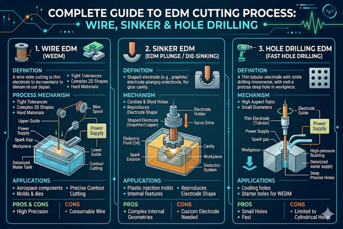
EDM Cutting Process Explained: Wire, Sinker & Hole Drilling EDM — Tolerances, Materials, and When to Use Each
| Process Types | Wire EDM, Sinker EDM (Ram EDM), Hole Drilling EDM |
| Wire Diameter | 0.004″–0.012″ (0.10–0.30 mm) brass or copper |
| Wire EDM Tolerance | ±0.0002″ (5 µm) after skim passes |
| Sinker EDM Tolerance | ±0.0005″ (12 µm) |
| Hole Drilling Tolerance | ±0.002″ (50 µm) |
| Surface Finish Range | Ra 0.1–12.5 µm (depending on type and passes) |
| Dielectric Fluid | Deionized water (wire) / Hydrocarbon oil (sinker) |
| Materials | Any electrically conductive material |
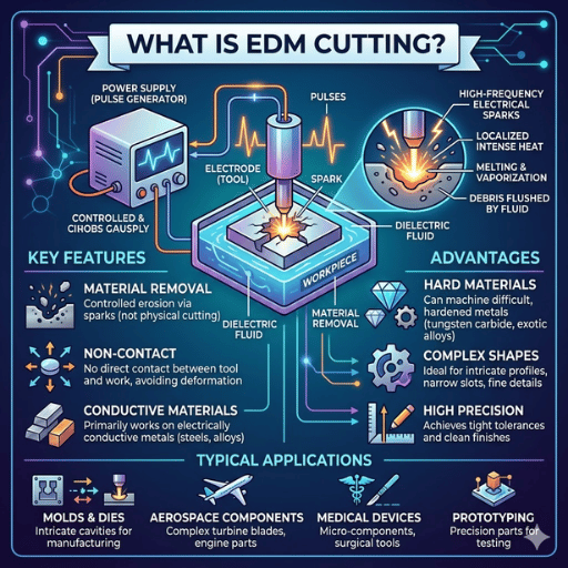
EDM cutting (electrical discharge machining), or spark machining/wire cutting, is a machine process that uses electrical discharge rather than engender direct contact to remove material. EDM cutting can cut any conductive metal no matter how hard, and is therefore the automated process of choice for producing cuts in hardened tool steels, tungsten carbide and superalloys that would destroy cutting tools used in more traditional machining tasks. From die profiles to deep mould cavities to micro-diameter cooling holes, one of the three EDM variants will do the job.
Learn more about Le Creator’s wire EDM services for precision profile cutting.
Here is how EDM functions as a machining process. It consists of two conductive bodies: a tool electrode and a work piece in a dielectric fluid. No action occurs when voltage is supplied, usually between 40-300 V up to 50 A if in DC as the dielectric fluid covers an insulator which results in no flow of electric current.
The electric field increases as the gap decreases as the electrode approaches the work. When the electrode work gap drops to 0.001″-0.002″ (25-50 m), a breakdown occurs in the dielectric. A plasma channel is formed between electrode and work that conducts electrical current during a short pulse (microseconds).
Temperatures for the plasma channel in excess of 8,000 C to 12,000 C-this is well above the melting point of any engineering metal.
In each pulse a small volume of material from the work piece, and electrode surface, starts to erode as it melts and vaporizes. Once the pulse finishes, the plasma collapses and the dielectric rushes into the tool, flush away the molten debris as microspheres (generally 1-30 μm in diameter). This process continues repeatedly at a high frequency of 1-500 kHz, so each spark extends a known and reliable depth of kerf.
Since the electrode never actually touches the workpiece, the Cutting forces involved in the process are nil. This prevents any form of mechanical stress and deflection of the tool, and no distortion of delicate or thin features is to be seen. No material hardening occurs – grinding HRC 65 tool steel is an easy task, as EDM sparking occurs purely upon electrical and thermal characteristics, not mechanical properties.
Two basic parameters—pulse on-time and pulse off-time—are maintained by the operator. A greater duration of the pulse on-time results in a greater quantity of energy being delivered to the spark, which results in a high MRR, a rough surface, and a substantial depth of the recast layer. Shorter duration of the pulse on-time causes the opposite.
📐 Engineering Note
Spark gap: 25-50 m. Discharge energy: 0.1-1,000 J/spark. Reference: ISO 11559 – provides definitions for traditional EDM terminology and procedure parameters.
The power pulse on:off-time ratio fully determines the nature of the surface finish compared to the material removal rate- a 1:3 (on:off) ratio is the best combination for finish whereas a 3:1 (on:off) ratio is best for speed. Contemporary generators vary this ratio automatically in a maximum of 64 separate power levels.
These four types of EDM all using same theory of spark erosion. Their difference is: the electrode geometry, dielectric, and motion system are different for different features.
| Feature | Wire EDM | Sinker EDM | Hole Drilling EDM |
|---|---|---|---|
| Electrode | Brass wire 0.004″–0.012″ | Graphite or copper (shaped) | Brass tube 0.010″–0.118″ |
| Dielectric | Deionized water | Hydrocarbon oil | Deionized water |
| Tolerance | ±0.0002″ (5 µm) | ±0.0005″ (12 µm) | ±0.002″ (50 µm) |
| Surface Finish | Ra 0.1–3 µm | Ra 0.4–12.5 µm | Ra 0.3–3.2 µm |
| Geometry | 2D profiles (with taper ±30°) | 3D cavities | Through-holes only |
| Best For | Precision blanking, gears, extrusion dies | Mold cavities, die impressions | Start holes, turbine cooling holes |
| Speed | 3–15 in²/hr | 0.1–0.4 in³/hr | 30–60 sec per hole |
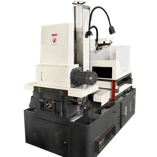
Constant spooling brass or coated wire (most often 0.010″ / 0.25mm diameter) travels vertically through the work – just like a bandsaw blade – except it never touches. The wire snaked from a supply spool through diamond guides, over the cutting zone, and onto a take-up spool. Since the wire constantly advances, electrode wear doesn’t matter; each section of wire is used once only.
Wire EDM produces the tightest tolerances of any edm process using a series of skim passes – light finishing passes that remove less and less material. Typical steps: rough cut Ra 3 m, first skim Ra 1.6 m, second Ra 0.8 m, third Ra 0.1 m. Each skim adds to machining time, but produces finer dimensions and a better surface.
Sinker EDM employs a pre-shaped electrode – ground from graphite or copper – that is plunged into the work to produce a hard mirror-image cavity. The electrode shape is taken directly onto the work piece, making sinker EDM the go-to process for injection mold cavities, forging dies, die-casting tools. Deep 3D shapes with depth to width ratio over 20:1 are easily machined.
Hole drilling edm (also called fast-hole or small-hole edm) feeds a spiraling brass tube electrode down through the work. Dielectric fluid spills through the hollow center and flushes debris from the bottom of the hole. Hole diameters from 0.010″ to 0.118″ (0.25-3.0mm) are drilled in up to 12″ deep steel, titanium, tungsten carbide, any conductive work always the same operation – of course drilling is always in addition to other machining operations. Frequently makes hole start points for wire ED machining paths.
✔ Advantages
⚠ Limitations
The recast layer – also called the white layer – develops when molten material re-freezes on the surface instead of flowing away. The hardened brittle layer has microhardness values 30-50% greater than substrate. Specifications such as AMS 2628 demand complete removal of the recast layer for aerospace and medical components.
The material removal rate varies hugely by workpiece material. Steel, for instance, typically takes 160-400 mm/hr on sinker EDM, whereas tungsten carbide drops to just 40-100 mm/hr at roughly identical process parameters. Titanium is quickly machined via wire EDM as deionized water prevents the oxidation nightmare associated with traditional machining of it. EDM works on any conductive material regardless of hardness – a major advantage versus other machining processes.

Choosing between EDM, CNC machining services, and laser cutting depends on minimum material hardness, feature shape and size, tolerances, and production volume. Each process has a distinct operating window.
| Parameter | Wire EDM | CNC Milling | Laser Cutting |
|---|---|---|---|
| Tolerance | ±0.0002″ (5 µm) | ±0.001″ (25 µm) | ±0.004″ (0.1 mm) |
| Surface Finish | Ra 0.1 µm | Ra 0.8 µm | Ra 1.6 µm |
| Materials | Conductive metals only | All metals + plastics | Sheet metal (thin) |
| Internal Corners | Sharp (wire radius ~0.005″) | Requires tool radius (min ~0.015″) | N/A (through-cut) |
| Cutting Force | Zero | High (requires rigid fixturing) | Zero |
| Hourly Rate (US) | $40–$120 | $40–$120 (3-axis) | $60–$125 |
| Best For | Hard metals, tight tolerance, complex profiles | General machining, fast cycle times | Sheet cutting, high volume |
Decision tip: Most costly per feature for hardened materials over HRC 45 and requiring internal features to 0.001″ or tighter is EDM. For softer metals with open geometry, CNC milling services will be faster and cheaper per part.
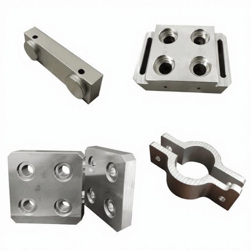
Numerous high-precision parts pair processes. For example, CNC machine a pair of mold bases to shape and finish the external geometry, then use sinker EDM to finish internal cavities and deliver sharp corners. This hybrid process takes advantage of fastest milling for the external features and shape, and then adds the geometric precision of EDM. For multi-sided parts requiring indexed setups, 4-axis CNC machining can reduce handling before the part moves to the EDM cell.
Laser cutting targets high-speed sheet metal profiling (1,000 in/min or 25 m/min on thin gauge steel) but cannot deliver tight EDM tolerances or cut through thick sections. While laser cutting is limited to under 1″ (25 mm) sheet thickness for most metals, wire EDM can cut through 12″ (300 mm) with consistent accuracy top to bottom.
Demand for turbine engine components represents a large portion of EDM demand. Inconel 718 turbine blades require hundreds of cooling holes—0.2-0.5 mm diameter—drilled through material hardened to HRC 44. Hole drilling EDM delivers 0.005 mm process accuracy for these features across thousands of blades, resulting in 40% time savings compared to traditional drilling. Wire EDM also shapes fir-tree root forms on turbine disks to 0.0003″ accuracy through interrupted profiles. Explore more at aerospace CNC machining.
Titanium orthopedic implant fixtures use sinker EDM to generate regular surface textures that promote osseointegration. Accuracies of 0.005 mm guarantee identical pore dimensions. Medical instrument parts, for example micro-scissors and biopsy forceps, use wire EDM to produce profile features where burr-free edges are not optional but essential. Read about medical device CNC machining for broader context.
Cavities for injection molds with aspect ratios over 20:1, 0.030″ thick section ribs, and a mirror finish are high application for sinker EDM. Graphite electrodes on high-speed mill machines transfer complex 3D geometry into hardened H13 or S7 tool steels of HRC 48-52. Multi-cavity tools typically combine CNC rough machining (80% material removal) with subsequent EDMs finishing.
Wire EDM produces micro-connector pins with cross-sections below 0.5 mm, semiconductor lead frame tooling with 0.003 mm pitch tolerance, and mold cavities for IC packages. No cutting forces exist so fragile parts are not deformed.
Market Data: The worldwide market for EDM services was valued at $7.1 billion in 2024 and is anticipated to reach $9.8 billion in 2030 growing at a CAGR of 5.5% over the period. Demand is driven by aerospace turbine production, increased use of medical implants, and the upscaling of mold complexity driven by automotive electrification.
Design for EDM is different than designing for conventional machining. Use these to save time, money and revisions in your projects.
Our Perspective on This Guide
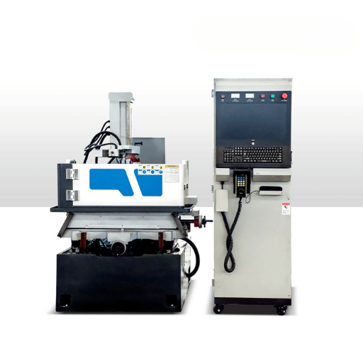
Le Creator operates our wire EDM machines in our Shenzhen (near Hong Kong) facility, delivering 0.005mm (0.0002″) tolerance on production runs. We are ISO 9001:2015 and IATF 16949 certified, with defined experience in aerospace turbine components, medical implant tooling. This guide is based on our shop floor experience, using real data from the field; the numbers are not approximations from the textbooks. When industry data are referenced, sources are provided below.

EDM cutting is a small-scale machining process that removes metal by rapid electrical sparks discharge through dielectric fluid. Each spark discharge reaches 8,000-12,000 C, coking a tiny amount of metal. The tool and part are not in physical contact giving the process no cutting forces and no effect from part hardness.
Three main types of EDM exist. Wire EDM, using a thin brass wire (0.004-0.012″) to cut 2D shapes, with 0.0002″ tolerance. Sinker EDM (or ram EDM) where a shaped graphite or copper electrode is lashed into the workpiece, creating 3D cavities, with 0.0005″ tolerance. Hole drilling EDM, where a hollow tube electrode is sent through the workpiece to form a through-hole, 0.010-0.118 in diameter.
The four main process parameters are: (1) the pulse on-time (spark duration & energy delivered); (2) the pulse off-time to allow dielectric to recover & debris to be expelled; (3) the wire tension (800-2,400 grams) which affects wire deflection and straightness of cut; (4) the wire speed (2-15 meters/min.) to keep fresh wire in cut zone at all times.
EDM of any electrically conductive material is possible even at very high hardness. Typical workpieces are: tool steel (up to HRC 65), Inconel, copper and aluminum alloys, tungsten carbide, titanium. Non-conductive material including ceramics, glass and plastics cannot be machined.
Finish relies on EDM type and number of finishing passes. Wire EDM produces Ra 0.1 m from 3 skim passes (mirror finish), starting from Ra 3 m, fine-cut rough bend. Sinker range Ra 0.4 m (fine cut settings, finish) Ra 12.5 m (rough bend). Hole drilling EDM range Ra 0.3 m (fine cut settings, finish) Ra 3.2 m (rough bend). Finer finishes are obtained with lower discharge energies and long machining times.
Ra 0.0002 and Ra 0.1 m finishes are obtained on EDM thick sections (>12″), Ra 1.6 m (laser cut) with top tolerance of 0.004″ and Ra 1.6 m; best result with sheet-metal of <1″, fast for thin profiles. For thicker sections, EDM is more sluggish, but feasible and better for hardened metals, internal features inaccessible to laser cutters.
Ready to get you EDM job started? Upload your CAD file for a free estimate – most quoted within 12 hours.
Related Articles
References