Supportive, Professional, Client-Focused Service
Get in touch with Lecreator Company
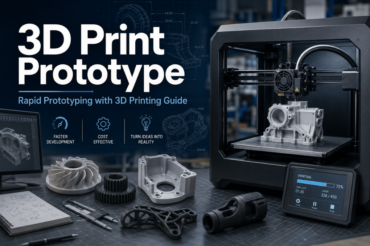
From prototypes to full-scale production, we’ve got you covered.


For most teams, the strength of using 3D printing for prototyping emerges in areas such as shape, fit, assembly sequence, ergonomic feel, wire routing, or early functional test. That same technique falls short in the areas of final material properties, complete reference datums, cosmetic surface finish, thermal cycling, or continuous load in production use.
This document considers 3D printers as one of several manufacturing approaches in a broader prototype plan. It compares common 3D printing methods, plastics, CAD drawing options, tolerances, test costs, and the point where a prototype is ready for CNC machining service, soft tooling, or injection molding.
For product development teams, prototyping with 3D printing works best when each build answers a named manufacturing process question. 3D printing for rapid prototyping can compare FDM, SLA, SLS, MJF, and other 3D printing technologies before traditional methods such as CNC machining or injection molding take over. If the model comes from SolidWorks or another CAD system, export both the print file and the engineering file when dimensions matter.
| Best fit | Concept models, housing mockups, ergonomic checks, assembly trials, fixture ideas, and early functional prototypes. |
|---|---|
| Weak fit | Final tolerance proof, molded texture approval, long-life load tests, high-heat service, or exact metal behavior. |
| Common processes | FDM, SLA, SLS, MJF, PolyJet, and metal 3D printing. |
| Common files | STL for mesh printing, STEP for engineering review, 3MF when units, color, or build data matter, and OBJ for visual models. |
| Best next step | If the design has real loading, mating faces, or a production date, send the CAD file for rapid prototyping service review instead of choosing by printer name alone. |
Additive manufacturing, simply expressed, produces a tangible item from a CAD design by layering plastic or metal material. NIST describes additive manufacturing as building three-dimensional products from digital designs, which is why a printer can shorten the distance between CAD and a test item.
However, a printed “prototype” is not yet a product prototype. Parameters like direction of build layers, choice of grade, orientation, support removal process, curing, powder removal, density, surface quality, measurement technique each affect the physical object delivered.
| A printed prototype can test | A printed prototype should not be asked to prove alone |
|---|---|
| Shape, size, and visual intent | Final molded texture, gloss, or color approval |
| Basic assembly order and access | Long-run wear under production loading |
| Ergonomic feel and human interaction | Final thermal, chemical, or UV behavior |
| Early fluid, airflow, or cable-routing checks | Certified pressure, fatigue, or safety margins |
| Fast design iterations before tooling | Final unit cost at 5,000, 10,000, or higher production volumes |
TWI defines rapid prototyping as the fast production of a physical item, model or assembly from 3D CAD, mainly through one kind of additive manufacturing. Success depends on what that prototype is required to demonstrate.
FDM usually demonstrates the shape and size aspect of the part at low cost. SLA and other resin printers demonstrate fine detail and visual effect. SLS and MJF demonstrate nylon-ready functional aspect with less surface marks from support points. PolyJet demonstrate multi-material, multi-color presentation capacity. Metal 3D production is more suited to complex metal shape. Choose it after considering whether you will need a second processing step of inspection or machining.
| Process | Best prototype use | Main caution | Typical handoff |
|---|---|---|---|
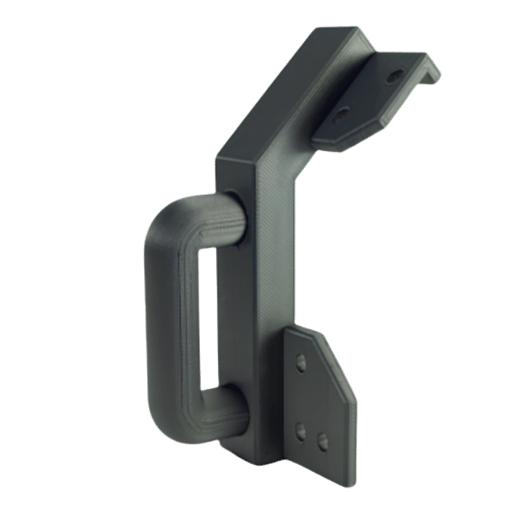
| FDM | Large plastic models, brackets, fixture ideas, early housings | Layer lines, anisotropic strength, and lower detail | ABS CNC machining or molded ABS when final fit matters |
| SLA | Fine detail, clear features, cosmetic review, small enclosures | Resin behavior may not match final thermoplastic | CNC plastic or injection molding after geometry approval |
| SLS | Functional nylon prototypes, clips, housings, complex ducts | Powder texture and dimensional variation need review | Nylon CNC machining or bridge tooling |
| MJF | Repeatable nylon parts, small batches, living-hinge trials | Surface color and fine cosmetic needs may need finishing | Low-volume production or molded nylon if volume rises |
| PolyJet | Color, soft-touch zones, overmolded look, medical models | Material may be presentation-grade, not production-grade | SLA, urethane casting, or tooling review |
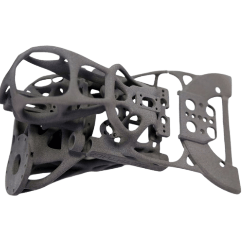
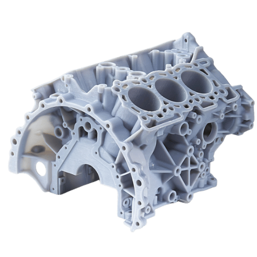
| Metal 3D printing | Internal channels, lattice structures, lightweight metal concepts | Heat treatment, supports, inspection, and machining stock matter | aluminum CNC machining, stainless steel machining, or hybrid finishing |
Common 3D printing applications include concept models, physical prototypes, high-fidelity prototypes, fixtures, functional parts, and small batch production parts. Rapid prototyping with 3D printing helps product development teams create custom samples without tooling, review design decisions, and get prototypes quickly into a meeting or lab test. Compared to traditional manufacturing, the main gain is shorter lead times during learning; traditional manufacturing still matters when final material, tolerance, and repeatability take priority.
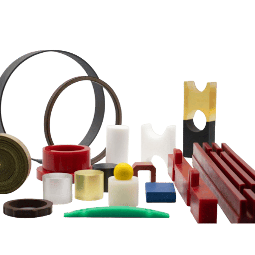
Material choice needs the same discipline. 3D printing materials range from thermoplastic filament to resin, nylon, polycarbonate, flexible polymers, and metal powder, and each one changes surface finish, chemical resistance, temperature resistance, and mechanical properties. A physical model that only looks and feels right may be enough for industrial designers, while end-use parts need stronger proof of material behavior.
Cost per part should be reviewed beside part cost risk. An instant quote can be useful for early budgeting, but cost efficiency depends on whether teams need to print parts once, iterate through multiple revisions, or bridge into low-volume production. For computer-aided design workflows, keep the digital model, drawing notes, and print file together; this makes it easier for teams to test fit, function, and inspection from the same revision rather than different materials or mismatched revisions.
When your prototype includes tight bores, journal seats, seals, or repeatable sliding interfaces, plan for machining stock, inserts, reaming, tapping, or secondary CNC milling after printing. When the shape is shaft-like or sleeve-like, CNC turning may answer the prototype question faster than printing.
NIST research into design practice suggests additive manufacturing selections should reflect process capability, material properties, surface quality, size, and tolerance requirements. That is why selection should be test-goal first, material second.
| Prototype situation | Good starting material/process | Why it fits | Watch point |
|---|---|---|---|
| Low-cost housing mockup | FDM PLA or ABS | Fast shape check before design review | Layer strength and finish limits |
| Functional snap-fit trial | SLS or MJF PA12 | Nylon handles flex better than many brittle resins | Clearance and fatigue still need test cycles |
| Transparent flow or light path check | Clear SLA resin | Visual access to internal features | Polishing and sealing may change dimensions |
| High-heat plastic check | High-temp resin, PEEK path, or machined PEEK | Better fit for heat exposure studies | Printed and machined behavior can differ |
| Electronics enclosure | FDM ABS, SLA, or MJF nylon | Good for board clearance, buttons, bosses, and ribs | Thread strength and repeated screw cycles |
| Fixture or jig concept | FDM, MJF, or machined plastic | Quick proof of locator and clamp geometry | Wear faces may need metal inserts |
| Lightweight metal concept | Metal 3D printing or titanium machining | Good for complex geometry or strength-to-weight ideas | Inspection, heat treatment, and support scars |
| Visual investor demo | SLA, PolyJet, painted FDM, or urethane casting | Appearance matters more than fatigue life | Do not reuse as a final engineering test sample |
| Production material check | CNC from final resin, metal, or molded trial | Closer to end-use mechanical behavior | 3D printing may no longer be the main process |
Selection of material should also be guided by sourcing constraints. Rough physical concepts may only need a simple printed plastic. Designs near heat, solvent, repeated assembly, or load may require a secondary machining route with machined acrylic, ABS, nylon, PEEK, aluminum, stainless steel, or another metal after the first plastic prototype.
Cost of the prototype is rarely driven by material choice, but by build volume, machine use, required finish, quantity required, time pressures, and ability of a first CAD file to be correct.
Lecreator lists starting points on its 3D printing service page for FDM, SLA, SLS, MJF, metal, and large-format printing, but those numbers should be read as quote starting points, not standard prices. Thin enclosures can have the same bounding box as thick brackets but take twice as much machine time.
| Cost driver | What to send with the RFQ | Why it changes the quote |
|---|---|---|
| Part envelope | Length, width, height, and orientation limits | Large parts may need longer builds or segmentation |
| Wall thickness | Minimum walls, ribs, bosses, and snap features | Thin walls fail; thick walls raise print time and risk |
| Surface finish | As-printed, sanded, painted, vapor smoothed, or plated | Finishing adds labor and may change dimensions |
| Quantity | 1, 5, 20, 50, 500, or pilot-batch target | Batch nesting helps some processes but not every geometry |
| Inspection | Critical dimensions, datums, and pass/fail limits | Inspection time can exceed print time on small critical parts |
| Deadline | Standard, express, or fixed demo date | Rush work may need machine priority and simpler finishing |
If you need a prototype this week, it pays to clarify the scope before asking Lecreator for a quote. Send the CAD file, a drawing if you need tight tolerances, the number of units, the preferred material, what final use it will have, any finishing requirements, and a note saying exactly what cannot move in the design.

Many failed 3D print prototype jobs get stopped before building. Maybe the model is non-manifold, maybe the file doesn’t have units, maybe the fine features are below the process limits, or maybe the team just sends an STL instead of a STEP for design review.
Lecreator’s guide to file formats separates STL, STEP, 3MF, and OBJ by type of geometry, color data, unit data, editable geometry, and common industry use. That matters because a mesh file might be printable but not helpful for tolerance discussion.
| Upload check | Preferred evidence | Why it matters |
|---|---|---|
| Units | STEP, 3MF, or drawing note in mm/inch | A 25.4x scale error can ruin a rush job |
| Watertight mesh | Repaired STL or 3MF | Open edges and self-intersections can block slicing |
| Mating clearance | Assembly file and target gap | Lecreator’s guide notes 0.2-0.3 mm clearance as a practical starting point for mating parts |
| Hole allowance | Hole callouts and post-drill permission | Printed holes can close, ovalize, or show stair-step edges |
| Critical faces | Drawing with datums and surface notes | Critical faces may need machining, sanding, or different orientation |
| Threaded features | Insert, tap, or printed-thread instruction | Repeated fastener use often needs inserts or machined threads |
| Build orientation | Preferred load direction and cosmetic faces | Orientation affects layer strength, finish, and support scars |
| Material substitute | Final material target and allowed substitute | A resin sample may approve shape but not final mechanical behavior |
| Revision control | Part number, revision, and date | Fast iterations become risky when files are renamed loosely |
The values below are not promises that every 3D printing process can hold. They are the project baseline fields an engineering team should replace with its own drawing data before quote review.
| Project evidence field | Example value to record | Production risk it controls |
|---|---|---|
| Mating clearance baseline | 0.2 mm to 0.3 mm starting gap | Prevents a project timeline from being reset by avoidable assembly rework. |
| Small feature baseline | 1 mm rib, 2 mm wall, or 5 mm boss called out on the drawing | Keeps the first prototype project from approving features that cannot be inspected. |
| Hole and bore baseline | 3 mm pilot, 5 mm screw clearance, or 10 mm bearing bore | Reduces rework rate when drilled, reamed, or tapped features are required. |
| Machining stock baseline | 0.5 mm to 1 mm stock on a datum or sealing face | Protects the production outcome when printed surfaces must become measured faces. |
| Inspection baseline | 0.05 mm, 0.1 mm, or 0.2 mm limit on a critical feature | Clarifies whether the prototype project needs measurement, not just visual approval. |
| Envelope baseline | 100 mm, 300 mm, or 500 mm maximum part envelope | Prevents late splitting, bonding, or fixture decisions that slow throughput. |
| Lab load baseline | 10 kg, 25 kg, or 50 kg trial load | Keeps a project team from treating a visual model as a load-bearing case study. |
| Heat and electronics baseline | 60 C, 80 C, 120 C, 12 V, 24 V, 1 A, 5 A, or 10 W operating note | Connects material choice to the real deployment environment, not just CAD shape. |
| Finish and schedule baseline | 0.1 mm layer cue, 0.2 mm sanding allowance, 24 hr quote need, 48 hr build need, or 72 hr demo date | Shows whether the project timeline favors printing, machining, or a simpler finish. |
| Release planning baseline | 1 month pilot, 3 months tooling review, or 12 months production outcome | Separates a one-off prototype project from an actual production outcome. |
If you need accuracy, ask whether the supplier recommends printing near-net and finishing some features by machining. Lecreator’s guide notes that some critical dimensions may need subsequent machining, which is a better plan than expecting every printed surface to behave like a machined datum.

Once a design is stable, a 3D print prototype should not be used every time going forward. Later prototypes will probably need final material, improved surface finish, tighter inspection and measurement, or consistency as good as injection-molded parts.
When a 3D print prototype no longer makes sense, move toward CNC machining if the next iteration will need accurate datums, threaded metals, smooth sealing faces, bearing bores, predictable alloy or resin response, or an inspection report tied to the drawing. Move toward injection molding or bridge tooling if your goal involves molded texture, living hinges, parting lines, ejector marks, gate vestige, shrink, or part cost at volume.
In fact, sheet metal should be part of your plan if it turns out the part is really an enclosure, bracket, chassis, or panel. In that scenario, a printed model can verify space fitting, but the next engineering prototype probably belongs in sheet metal fabrication.
| Trigger signal | Stay with 3D printing if… | Move away if… |
|---|---|---|
| Design is changing daily | Engineering team needs physical feedback after each revision | Revision is locked and only production risk remains |
| Quantity rises above pilot size | Geometry is complex and batch printing still makes sense | Unit cost depends on tooling or machining cycle time |
| Tolerance becomes the test | Loose fit is enough for the stage | Datums, bores, and sealing faces drive acceptance |
| Material behavior matters | Printed substitute is accepted for learning | Final resin, alloy, fatigue, heat, or chemical behavior is under test |
| Appearance is critical | Painted or sanded prototype is enough | Molded texture, gloss, and parting lines need signoff |
Whatever the decisions based on form and fit, the 6-Gate Prototype-to-Production Readiness Map provides a straightforward guide to say whether a printed part should stay as additive, move to CNC machining, or complete the progression toward tooling. Each gate remains under the simple owner’s control and with a yes/no pass/fail rule.
| Gate | Question | Pass evidence | Likely next process |
|---|---|---|---|
| Gate 1: Form | Does the physical shape match the design intent? | Stakeholder signoff on size, access, and visual layout | FDM, SLA, or PolyJet |
| Gate 2: Fit | Do mating parts assemble without force or rattle? | Measured clearances and assembly notes | SLS, MJF, or machined plastic |
| Gate 3: Function | Does it survive the intended test cycle? | Load, cycle, heat, or fluid test result | Nylon print, machined plastic, or metal |
| Gate 4: Finish | Does the surface meet the user’s expectation? | Photo approval, roughness target, or finishing sample | SLA, painted print, machined part, or molded trial |
| Gate 5: Inspect | Can the critical dimensions be measured and repeated? | Drawing, datum plan, and inspection report | CNC, hybrid printed-plus-machined part, or fixture |
| Gate 6: Scale | Does the process still make sense at the next quantity? | Costed path for 10, 100, 500, and production volume | Batch printing, CNC, bridge tooling, or injection molding |
Use this map before asking for a second or third prototype. Map use keeps fast multiple iterations on track. Suppliers have enough detail to recommend the right route rather than simply providing the price for the process named in the e-mail subject line.

Prototyping is no longer limited just to additively manufactured concept models. ASTM Committee F42 on Additive Manufacturing Technologies was established in 2009 and reports over 743 members with eight technical subcommittees. This is important, because prototype teams are now calling upon printed parts for more formal engineering evidence.
Work on standards continues. America Makes and ANSI’s AMSC roadmap identified 141 additive manufacturing standardization gaps. Of these, 54 are high-priority gaps and 91 need additional pre-standardization research and development before standardization can be considered. Buyer message is straightforward: be explicit about the design proof points, and be cautious about accepting one print result as universal data.
For Lecreator’s target audience, that points to a practical hybrid path. Use 3D printing service for speed, shape, and early function. Use CNC machining when dimensions, materials, or inspection need to be closer to final manufacturing. Use molding or bridge tooling when volume, molded behavior, and unit economics become the main question.
When these parameters are defined, send the file through Lecreator’s contact page or the rapid prototyping quote path.
Yes. A 3D printer can produce a prototype that visually follows the CAD model, usually from STL, STEP, 3MF, or OBJ data. Before printing, the team should define the test goal: shape, fit, function, appearance, or production planning. Without that goal, the part may look successful while answering the wrong engineering question.
Price depends on volume, size, finish, processing, material, and wait time. Send the CAD file and goal use to get a relevant cost estimate.
For a unique or low-volume plastic functional prototype, nylon SLS or MJF is often a sensible starting point. FDM can work for early brackets and fixtures, while SLA suits detailed appearance samples. Metal 3D printing fits complex metal shape when inspection criteria, post-machining, and post-processing are part of the plan. Confirm the test loading, build position, and subsequent machining before final production use for load-bearing parts.
STL is the open standard for mesh print-fidelity. STEP is an engineering standard capable of carrying solid-model information while providing the engineering reviewer the precision information they need. 3MF is an additive manufacturing capable file format that can include the build data and parts unit context.
Proceed to CNC machining when the prototype test involves critical or restrictive circumference measurements, sealing surface quality, hard plastics or metals final behavior, productive threads, or analytical inspection. Additively manufactured model may still balance the design team, but the next batch may need to be helped by machined features. This is pretty normal for critical hole placement, bearing cushion, tapped threads, sliding landing, and sealing seal land circumstances; often looking for a few tenths of a millimeter is the critical visualization metric and avoid both failed printing and engineer disapproval.
Printed part additions can be used to avoid initial tool creation; they cannot match molded quality, shrinkage, gate position, or production rate because each part built costs the same.
Establish mating clearance, show critical datums, flag post-machined features, and provide the assembly context. For snap fits, through holes, bosses, and sliding features, leave room for iterations because printed datum locations can shift with orientation, material, and post-processing.