

Supportive, Professional, Client-Focused Service
From prototypes to full-scale production, we’ve got you covered.


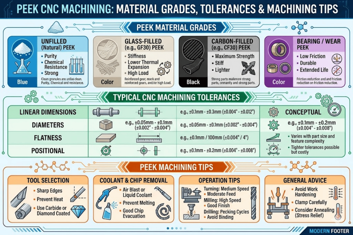
What Is PEEK CNC Machining? A Practical Guide to Grades, Tolerances, and Machining Parameters
peek is one of the toughest of the plastics to machine accuratly, and one of the most satisfying. A single poor feed rate or interrupted annealing step can recycle a component worth hundreds of dollars—yet when dialed-in, peek cnc machining produces parts that with stand jet-engine heat, attack from aggressive solvents, and stand in for heavier metal equivalents in medical, aerospace, and semiconductor service.
This guide explores the material science behind polyetheretherketone, examines popular peek cnc machining services, and provides the tested speeds, feeds, and annealing protocols that separate a good peek part from a scrapped one.
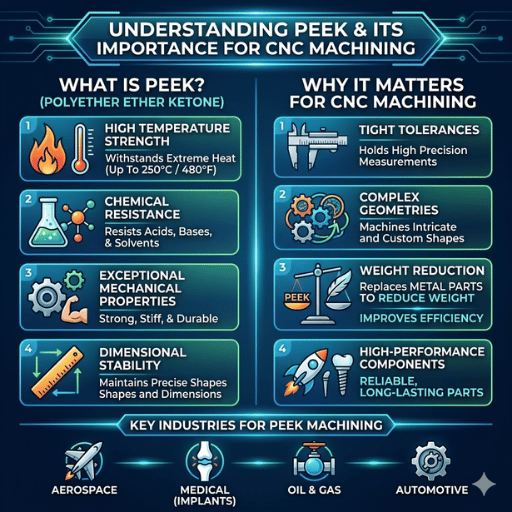
peek (polyetheretherketone, also polyether ether ketone) is a semi-crystalline thermoplastic of the poly-aryl-ether-ketone family, first synthesized by Imperial Chemical Industries in 1978 with commercialization following in the early 1980s. PEEK distinguishes itself from general plastics such as nylon or acetal by maintaining mechanical strength and stiffness at temperatures exceeding 200 °C and resisting industrial solvent exposure. This combination of mechanical and thermal properties makes peek a preferred alternative to metals in weight-sensitive designs.
Source: Victrex PEEK Material Properties Guide
These properties make peek cnc machining appealing to engineers under weight reduction constrains. A peek part can be as much as 70 % lighter than a similar stainless-steel part and have equal or superior fatigue life when facing corrosive chemicals. The high-performance thermoplastic also passes ISO 10993 biocompatibility testing, leading to the use of high-grade PEEK in spinal cages and dental abutments.
For machinists, peek comes between PTFE (which deforms unacceptably under tool pressure) and standard engineering plastics like peek plastic or POM in consistency. Grasping this balance is the foundation of successful peek machining.
peek combines fluorocurrency chemical resistance with the mechanical properties found in certain metals—making it the best choice for demanding cnc machining applications.
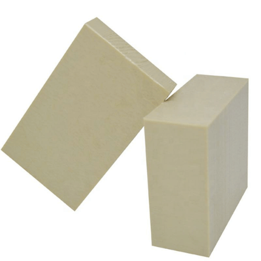
Your choice of peek grade directly controls tool-wear rates, achievable tolerances, and final part properties. Below we compare the five most popular grades for cnc machining projects in our shop.
| Grade | Filler | Tensile Strength | Max Temp | Best For |
|---|---|---|---|---|
| Unfilled PEEK (Victrex 450G, Tecapeek) | None | 100 MPa | 260 °C | General-purpose precision components, food contact |
| Glass-Filled PEEK (30 % GF) | Glass fibers | 157 MPa | 260 °C | Aerospace brackets, structural inserts |
| Carbon-Filled PEEK (30 % CF) | Carbon fiber | 212 MPa | 260 °C | Orthopedic implants, high-load bearings |
| Bearing Grade (PEEK PVX) | PTFE + graphite + carbon fiber | 68 MPa | 260 °C | Self-lubricating bushings, thrust washers |
| Medical Grade (PEEK-OPTIMA) | None (USP Class VI) | 100 MPa | 260 °C | Spinal cages, dental abutments, implant housings |
Unfilled peek provides the best machinability of any grade. It produces clean, curled chips and dimensional stability can be maintained across multiple-step operations. Glass filled PEEK, as well as carbon-filled formulations, increase the overall strength and stiffness of machined components but increase tool wear rates by 70-80 %. For all filled grades of PEEK, our machining specialists activate PCD tooling, which outlasts standard carbide inserts by 10-20x on abrasive reinforced blanks.
“The biggest mistake we see in our glass filled peek Zarobot is using the same unfilled speed and feeds you use on unfilled stock. The glass fibers destroy the cutting edges in minutes. Use PCD or diamond coated tools; nothing is too abrasive for filled peek.”
— Le-creator CNC Engineering Team
All grades discussed fall under the current ASTM D6262-23 specification for extruded and molded shapes. Meeting medical approval standards for peek requires ISO 10993 (biological evaluation of medical devices) and USP Class VI testing.
Identify the specific peek grade for the application, then adjust machining parameters accordingly. Filled peek increases cutting difficulties, requiring PCD tools and a downshift in cutting speed.
Appropriate machining parameters will prevent failures which account for the vast majority of burned-out plastic: heat induced surface glazing and stress induced warpage. Below are milling and turning parameters validated across thousands of peek parts on our shop floor.
| Operation | Cutting Speed | Feed Rate | Depth of Cut | Notes |
|---|---|---|---|---|
| Face Milling | 500-800 SFM | 0.006-0.035 in/tooth | 0.035 in | Use climb milling for best surface quality |
| End Milling | 270-450 SFM | 0.002-0.008 in/tooth | Up to 0.250 in | Step-over ≤25 % tool diameter |
| Turning | 300-800 SFM | 0.004-0.025 in/rev | 0.025 in | Sharp tools with positive rake angles |
| Drilling | 800-1500 RPM | 0.002-0.008 in/rev | Peck at 1x dia | Through-coolant drills preferred |
Unfilled peek parameters. Reduce speed by 20-30% for glass-filled or carbon-filled variants.
Tool selection matters as much as machining parameters. For unfilled peek milling and turning, uncoated C-2 carbide insert tips with sharp cutting edges and positive rake angles for smooth, crowned chips. Worn tools build up friction heat in the cut zone rather than shearing, resulting in surface glazing and wave-like distortions on the finished surface. PCD inserts are mandatory for all filled grades, as glass fibers and carbon fiber fillers are highly abrasive against standard carbide.
PEEK has a low thermal conductivity (0.25 W/m K), in other words heat less effectively conducts out of the tool/workpiece interaction but tends to huddle at the interface. Use the default peek cooling medium of choice; compressed air, approved water soluble Coolants or run dry with aggressive chip evacuation. Running dry relies on the peek chips themselves to carry heat away from the cut zone.
Run down to minimal depth of cut and without the benefit of fresh sharp cutting edges. peek does not behave like aluminum; maximum edge life is a function of how efficiently the edge shears through the PEEK, not how aggressively you machine it. Grind or score worn edges prior to cutting past; do not rely on another one.
Sharp tooling, moderated depths of cut, and heat management remain non-negotiable in peek machining due to the abrasiveness of the material. These three factors drive predictable peek operation.

Tolerance capability of peek parts is dictated by both conditions of the process and the part. Condition of the process is determined by the Machining operation and whether or not the part is intermediate stress-relieved annealed. Without annealing, residual stresses from the molding or extrusion process can lead to dimensional drift of 0.1-0.3 % after machine, enough to induce a tight-tolerance feature to go out-of-spec.
| Tolerance Level | Range | Annealing Required? | Typical Application |
|---|---|---|---|
| Standard | ±0.005 in (±0.127 mm) | Recommended | Industrial bushings, seal seats |
| Precision | ±0.001 in (±0.025 mm) | Required (multi-step) | Aerospace connectors, semiconductor fixtures |
| Ultra-Precision | ±0.0005 in (±0.013 mm) | Required + climate-controlled CMM | Medical implants, optical housings |
| Process | Achievable Ra | Notes |
|---|---|---|
| Standard CNC Milling | Ra 1.6-3.2 μm | Adequate for most industrial plastic parts |
| Finish Pass Milling | Ra 0.8-1.6 μm | Reduced feed, fresh insert |
| Polishing (Medical) | Ra 0.2-0.4 μm | Multi-stage polishing, removes tool marks |
At Le-creator, we hold ±0.001 in on precision PEEK parts through multi-step rough machining and finish passes with intermediate annealing. Our four Zeiss CMM inspection stations function in a climate-controlled room to verify dimensional accuracy of every production lot.
Tight tolerances on peek are possible but require some annealing between roughing and finishing. Budget accordingly when quoting precision peek machining tolerances.
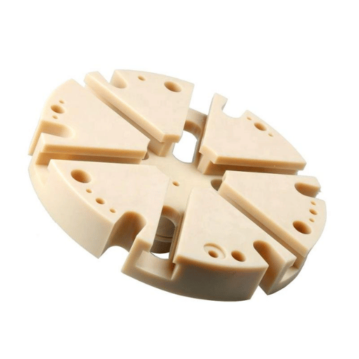
PEEK is not a forgiving plastic. Its demanding applications also produce machining characteristics that punish sloppy technique. Here are the four most frequent challenges our team faces, and the protocols that resolve them.
Root cause: peek has low thermal conductivity of 0.25 W/m K (205 W/m K is aluminum). Heat developed within the cutting contact zone does not diffuse outward into the workpiece.
Solution: Employ sharp tools with positive rake angles to support minimal friction. Keep depths of cut moderate. Blast with compressed air or employ mist coolant directed at the cutting tool. Track surface discoloration, the first immediate sign of heat related damage.
Root cause: Extrusion and molding peek blanks permanently deposit stress provinces within the work piece. Aggressive material removal introduces and releases these stresses unevenly, causing part distortion.
Solution: Remelt the stock at 160 C before machine. Ramp up 10 C/hr to 150-200 C, hold 3-4 hours (add 30 min every 3 mm cross section), and ramp down at 10 C/hr to below 148 C, spray cool. For tight-tolerance parts, employ a second anneal cycle between rough and fine machining. dimensional instability of finished peek parts normally goes back to unrelieved stresses from forced remelt.
Root cause: glass fibers and carbon fiber reinforcements are abrasive. Remove about ten times faster than unfilled peek.
Solution: Use PCD or diamond coated tooling when employed with glass or carbon filled premium peek grades. Decrease your cutting speeds by 20-30 %. Price accordingly when quoting for higher tool cost per part for filled grades.
Root cause: peek has enough ductility to yield in place rather than fracture in drilled and slot machined areas unsupported edges.
Solution: employ climb milling to drive cutting forces towards supported work material. Keep tools sharp with zero edge hone. When drilling, use a peck cycle and back-up the return surface with sacrificial material when possible.
Most peek machining failures trace back to heat and stress. Controlled cutting parameters, proper annealing, and sharp tools eliminate the majority of defects.
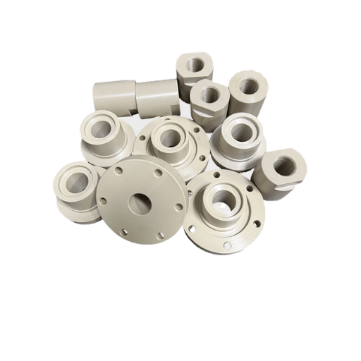
PEEK machined parts serve industries where failure is not an option and operating conditions exclude most other plastics. The global PEEK market reached an estimated USD 1.50 billion in 2025 and is projected to grow to USD 2.14 billion by 2030 at a 7.5 % CAGR, according to a MarketsandMarkets industry report. Aerospace, medical devices, and semiconductor manufacturing account for the largest share of CNC-machined PEEK consumption.
peek is the de facto material of choice for load-bearing spinal implants because its elastic modulus (3.5-4.5 GPa) is similar to cortical bone thus preventing stress shielding. It is also radiolucent and un-intrusive in post-op imaging. Typical PEEKmachined components include spinal fusion cages, dental abutments, surgical instrument handles, and endoscope housings. At Le-creator, a medical endoscope housing application, the rejection rate dropped from 22 % to 0.8 % after implementing dedicated stress-relief annealing protocols and cleanroom chip evacuation.
peek components are replacing aluminum and titanium brackets in non-structural aerospace applications, allowing weight reductions of up to 70% while withstanding continuous exposure to 260 C. Typical peek parts include cable routing brackets, electrical connectors, seal rings, and actuator housings. The material meets outgassing requirements for vacuum environments per NASA outgassing databases, which qualifies the polymer for satellite and space-vehicle components that meet strict contamination standards.
Wafer carriers, process chamber components, and end effectors are being machined from peek due to its chemical resistance to aggressive cleaning chemistries (piranha solution, HF vapor), low particulate generation and negligible outgassing. ESD-safe carbon-filled PEEK grades also shield sensitive wafers from electrostatic charge during handling.
Valve seats, backup ring seals, and compressor components exposed to H₂S, CO₂, and hot brine conditions benefit from peek’s chemical resistance and abrasion resistance. PEEK seals retain dimensional stability over pressure and temperature cycles that would degrade softer plastics like PTFE.
peek cnc machining serves industries where plastic components are exposed to exotic temperatures, corrosive chemistries, or biocompatibility requirements that disqualify commodity plastics.
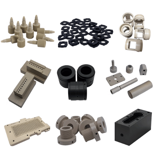
Both cnc machining and injection molding can produce peek plastic parts, but have different processing parameters. The decision comes down to volume, lead time, and tolerance requirements.
| Factor | CNC Machining | Injection Molding |
|---|---|---|
| Volume sweet spot | 1-5,000 parts | 5,000+ parts |
| Lead time (first article) | 1-3 weeks | 8-16 weeks (tooling) |
| Tolerance capability | ±0.001 in achievable | ±0.003-0.005 in typical |
| Tooling cost | None (program + fixture) | $15,000-$80,000+ for PEEK molds |
| Per-part cost at 100 units | $50-$300 | Not viable (tooling amortization) |
| Per-part cost at 10,000 units | $50-$300 (no scale benefit) | $5-$30 |
| Geometry complexity | Internal features, deep pockets | Draft angles, uniform walls |
| Material waste | Higher (subtractive) | Lower (near-net shape) |
peek injection molding requires mold temperatures in the 170-200 C range, and melt temperature of 370-400 C. The seemingly extreme processing temperatures require extremely sophisticated hot-runner molds created from hardened tool steel, thus initial tooling investments are more expensive. For prototypes, low-volume production, or parts with tight tolerances and complex internal geometry, CNC machining in PEEK is the faster and more cost-effective path. Injection molding wins when annual volumes exceed 5,000 units and the part design accommodates draft angles and uniform wall thicknesses.
Many projects start with CNC-machined prototypes to validate the design, then transition to custom PEEK components via injection molding only after volumes justify the tooling cost.
Use CNC machining for volumes under 5,000, tolerance-critical parts, and prototypes. Switch to injection molding when annual demand exceeds 5,000 and the part design can accommodate draft angles and uniform wall thicknesses.

From prototype to high volume production, Le-creator has been providing peek cnc machining services with 0.001 in tolerances, ISO 13485 quality systems and 17+ years of engineering plastic expertise.
Le-creator has machined PEEK components since 2012 across medical endoscope housings, aerospace connector insulators, and semiconductor wafer fixtures. The machining parameters and annealing protocols referenced in this article reflect what we have validated on our DMG Mori five-axis mills and programmable annealing ovens over thousands of production runs. Where external data is cited, we link directly to the source.