

Supportive, Professional, Client-Focused Service
From prototypes to full-scale production, we’ve got you covered.


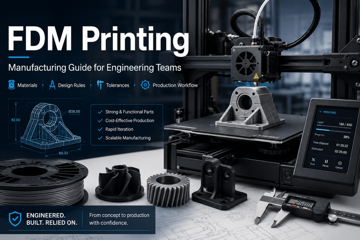
Though FDM printing is the first material extrusion process that most engineering teams get acquainted with, it should not be treated as a generic low-cost 3D print option. Whether an FDM part is a useful prototype, fixture, or failed build relies on the right parts, materials, orientation, and acceptance plan.
This guide explains how fused deposition modeling works, where FDM sits next to vat printing, SLS, MJF, and CNC, and how to tell when a file is ready for a production quote from a 3D printing service.
| Process family | Material extrusion additive manufacturing, often discussed as FDM, FFF, or fused filament fabrication. This 3D printer family builds the part from deposited thermoplastic roads. |
|---|---|
| Feedstock | Thermoplastic filament such as PLA, ABS, PETG, nylon, TPU, or carbon fiber filled grades, subject to printer and supplier capability. |
| Motion and bonding | Heated nozzle motion deposits softened polymer onto a print bed and previous layers; layer-to-layer bonding is a major strength driver. |
| Layer resolution band | Lecreator lists FDM service layer resolution at 100-300 micron for its service route. |
| Best-fit parts | Early 3D print prototypes, fixture bodies, ergonomic models, enclosures, large-format shells, and parts where layer lines are acceptable. |
| Watch points | Anisotropic strength, visible layers, support scars, warping, hole sizing, heat exposure, and inspection requirements. |
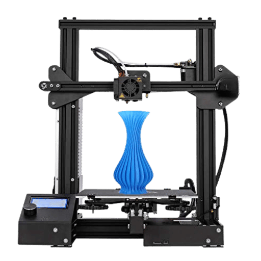
FDM printing uses material extrusion to create parts from thermoplastic materials and 3D model data. In routine engineering work, the terminology often intersects with FFF, because both refer to filament-based printers that melt material and deposit it in successive layers. Standards organizations place this activity inside AM, where objects are made by adding material rather than cutting it away.
Terminology note: FDM 3D printers are often sold as desktop 3D or professional 3D systems. FDM technology is one type of 3D printer in the wider 3D printing industry; the basics of FDM are simple, but an FDM machine still depends on FDM filaments, printing material, z axes, support material, and a stable build surface.
Historically, the FDM name is associated with Stratasys, while FFF became common in open hardware. A common desktop FDM setup can extrude 3D printing filament onto a build platform; industrial 3D systems add chamber control, larger build volume, print speed control, manufacturing process checks, manufacturing technology controls, and printing technology controls.
Search vocabulary can blur the market. Terms such as best 3D printer, popular 3D printer, advanced 3D printer, desktop 3D printer, and professional 3D printer often mix hobby machines with engineering needs. Ease of printing matters, but what is used in 3D printing varies by process. For serious applications, ignore generic 3D technology labels and compare material, inspection, load path, printing software, and supplier review.
That difference changes the starting point. A CNC milling path begins with stock and removes material. FDM starts with a digital model, a sliced toolpath, filament, a nozzle, and a build surface. It can produce a quick low-cost 3D print prototype, but the final part still carries the marks of its build path: bead width, layer thickness, infill, wall count, cooling, and orientation.
For teams already using rapid prototyping, FDM may be the fastest screening step before a tighter tolerance run, a molded tool, or a CNC machining service order.
The FDM 3D printing process seems easy at first: load the filament, heat the nozzle, move the print head, and construct the part layer by layer. In practice, each bead must bond to the road beside it and below it as the polymer cools. NIST work on material extrusion weld formation links part strength to the thermal history of welded zones rather than brochure-level printer specs.
Before the first layer is laid, a file usually passes through 6 decisions: model cleanup, process choice, material selection, layer setting, build orientation, and support strategy. A small decision in any of those steps can turn a part from acceptable to useless.
While a finer layer setting may increase the visible detail in a 3D print, it will also increase build time. A finer layer setting does not, in isolation, improve strength, warping, or similar concerns.
The extruder orifice determines how the material is laid down. Small holes, snap features, and thin ribs should be verified against bead width and orientation.
FDM parts tend to be weaker along layer lines rather than across deposited roads. Integrate load paths into the orientation plan as early as possible.
Part footprint, fan settings, enclosure control, and bed temperature affect first-layer hold and corner lift.
NIST thermography papers explain why the bonding window is short: the printed road cools quickly, and time above the polymer’s glass transition can be close to 1 second under tested conditions. Two 3D print jobs using the same layer setting can still produce different mechanical results.

FDM is not a single material domain. Unfilled, filled, and reinforced plastic materials all appear in ME work, and ISO/ASTM 52903-1 treats feedstock control as its own topic. Practically, the first material question should not be “What is cheapest?” It should be “What environment will this part see?”
| Material family | Why engineers choose it | Watch before ordering |
|---|---|---|
| PLA | Fast concept models, visual prototypes, and low heat indoor parts. | Heat resistance and impact behavior can limit functional use. |
| ABS | Enclosures, brackets, and parts that need more toughness than PLA. | Warping and enclosure control matter on larger builds. |
| PETG | General working prototypes, covers, and parts needing easier handling than ABS. | Stringing, surface finish, and flexible snap behavior should be sampled. |
| ASA | Outdoor housings and UV-exposed parts. | Thermal control and supplier availability need confirmation. |
| Nylon | Wear parts, clips, and load-bearing prototype shapes. | Moisture control and dimensional drift are important. |
| Carbon fiber filled nylon | Stiffer fixture bodies, gauge nests, and lightweight support parts. | Fiber-filled filament can be abrasive and can change failure mode. |
| TPU / TPE | Gaskets, bumpers, grip pads, and flexible prototype features. | Soft filament can limit fine detail and repeatability. |
| PC | Higher heat needs and stronger engineering prototypes. | Requires stricter temperature control than basic PLA or PETG. |
| PEEK / PEKK / ULTEM-type materials | High-performance material programs where heat and chemical resistance matter. | Machine class, material traceability, and post-process inspection are critical. |
If a printed prototype will later move to machined plastic, compare the prototype requirement with plastic CNC machining, acrylic, PTFE, and other production material routes before freezing the design.
FDM is useful, but it is not a tolerance-free process. The final part is affected by printer calibration, material, bead width, layer setting, build placement, support contact, and cooling history. NIST’s plastics AM roadmap points to measurement, standards, material lifecycle data, process modeling, and part performance as ongoing adoption barriers for plastics AM in production.
Do not accept an FDM part based solely on the layer setting. Request inspection of the load axis, wall count, hole dimensions, support contact, material performance, and the inspection method that will determine pass fail.
A visible layer line might be acceptable for a cosmetic mockup, but the inspection plan for a sensor or hardstop locating fixture should specify datum surfaces, key holes, and post-processable surfaces. For a load-bearing prototype, determine the point where the highest stress crosses layer lines.

Differences between FDM, SLA printing, SLS, MJF, and metal processes make selection more useful than forcing every file through one printer. Among 3D printing technologies, using FDM makes sense where time, cost, size, and thermoplastic behavior are more important than detail, surface, isotropic strength, or end material data. That first 3D print can expose risk before the team chooses a higher-cost route.
| Route | Choose it when | Shift away when |
|---|---|---|
| FDM | Prototype bodies, fixtures, large shells, enclosures, and thermoplastic test parts are in scope. | Fine cosmetic detail, tiny text, clear features, or smooth resin-like surface is central. |
| SLA printers | Surface finish, fine detail, and small features matter more than thermoplastic behavior. | FDM-like material behavior, larger size, or rough handling tests matter more. |
| SLS 3D printing | You need nylon-like functional parts without FDM support scars. | Simple form and cost pressure make FDM the better first pass. |
| MJF | Batch consistency, fine feature detail, and functional nylon parts are the main goals. | You only need a few rough-fit shells or early ergonomic models. |
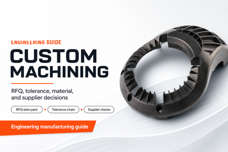
| CNC | Production material properties, tighter datums, threads, and finished faces are required. | The shape is still changing and the team needs fast 3D print feedback first. |
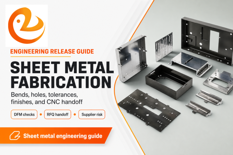
For metal housings, heat sinks, machined bosses, and flat functional faces, compare FDM output against aluminum CNC machining or sheet metal fabrication rather than asking a printed plastic part to act like metal.

FDM is often a good early-stage cost choice because it does not need hard tooling. Lecreator’s live service page lists FDM from $5 per part; final 3D print quotes still depend on geometry, material, quantity, finishing, and review criteria.
One trap is assuming that a cheap print is always a cheap engineering decision. An inexpensive FDM part that hides a fit issue can delay a program. A more careful pilot that tests hole fit, insert strategy, heat exposure, or surface finish can protect the later batch.
Best for early shape, hand feel, assembly envelope, and fast stakeholder review.
Test clips, holes, snap features, inserts, and thin walls before printing a full housing.
As quantity rises, ask whether SLS, MJF, urethane casting, CNC, or tooling now wins.
If you already have STEP or STL files, send them through the service channel and ask what the 3D print cost driver is: material, build time, support, finish, inspection, or part count. This is also where use 3D printing goals should be named clearly: fast learning, fit check, or a later bridge to another process. For uncertain files, use contact before settling on the process.
For a pilot project, treat the first order as a baseline rather than a finished production outcome. The table below is not a universal tolerance promise; it is a project review checklist for building a timeline, checking throughput risk, and deciding whether the next deployment should remain FDM or move to another manufacturing route.
| Pilot project check | Starting threshold to review | Project decision it protects |
|---|---|---|
| Layer baseline | Compare 0.10 mm, 0.20 mm, and 0.30 mm layer settings before freezing the surface expectation. | Prevents a timeline surprise when a fine layer setting doubles the print window. |
| Thin-wall screen | Flag walls below 1.2 mm and ribs below 2.0 mm for coupon testing. | Sets a baseline for whether the project needs redesign or another process. |
| Hole-fit coupon | Print 0.20 mm and 0.40 mm clearance offsets, then measure after 24 hr. | Reduces rework rate before the full fixture or enclosure project starts. |
| Flat-base check | Record corner lift at 0.5 mm and 1.0 mm, then decide if split printing is needed. | Protects assembly timeline when a large footprint part curls after cooling. |
| Insert trial | Test 3 mm pilot holes and 5 mm boss walls before committing to threaded inserts. | Separates a visual prototype from a field deployment part. |
| Heat exposure | Use a 1 hour and 2 hours exposure check when the part will sit near warm equipment. | Finds material risk before the project timeline depends on a plastic bracket. |
| Dimension sample | Measure 5 critical dimensions in mm and keep the same datum plan for the next run. | Creates a repeatable baseline for supplier review and later throughput comparison. |
| Rework trigger | Stop the route if rework exceeds 10% during a 20 hr pilot window. | Forces a process decision before low part price creates a slow project. |
| Throughput check | Compare an 8 hr print job with a 48 hr batch window before accepting the schedule. | Shows whether FDM is still useful after the prototype becomes a deployment batch. |
| Latch clearance | Check 0.10 mm, 0.20 mm, and 0.30 mm clearance gaps before trusting a snap-fit feature. | Keeps the project from treating one successful hand fit as a repeatable result. |
| Build queue | Compare 12 hr, 24 hr, and 48 hr queue windows before promising a review date. | Keeps the timeline tied to actual machine time, not only part price. |
| Surface mismatch | Flag 0.5 mm and 1.0 mm mismatch zones if printed surfaces locate an assembly. | Moves datum control to a safer process before rework rate rises. |
| Review loop | Reserve 2 hours for file review, 4 hours for supplier feedback, and 8 hours for revision. | Makes the project timeline visible before the first deployment batch is ordered. |
| Quote tolerance | Ask for review if quote assumptions shift by 10% after support, finish, or inspection is added. | Keeps the project baseline tied to the real production outcome, not just the first price. |
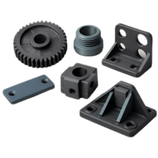
FDM performs near its best when the part’s task fits the process. It is often used for prototyping when teams need fast learning before committing to higher-cost methods. Good use cases usually follow one of 6 patterns: fast learning, coarse fit, hand feel, fixture body, protective shell, or large physical envelope.
This route is useful when the team needs a physical 3D print part before moving into tooling, molding, casting, or CNC.
Before CNC or tooling check access, cable path, enclosure space and human interface.
Print noncritical fixture structures, then add inserts, pads, or machined reference points if needed.
Use ABS or PETG or similar early in housing validation then look at heat and surface demands.
FDM can be practical for large display or ergonomic components when visible layer lines are acceptable.
Learn with printed parts then translate final need into CNC, molding, casting, SLS or MJF.

Run part files through this 9-gate process before sending them to a supplier. It turns standards-style order discipline into a practical file review. ISO/ASTM 52901 for purchased AM parts addresses part definition data, feedstock requirements, final characteristics, inspection, and acceptance methods.
| Gate | Pass signal for FDM | Escalate when |
|---|---|---|
| 1. Part purpose | Fit, form, fixture support, or early functional learning is the job. | It is a final safety, pressure, heat, or certified production part. |
| 2. Material duty | PLA, ABS, PETG, nylon, TPU, or filled filament fits the environment. | Chemical, flame, wear, or high-heat duty needs verified material data. |
| 3. Load axis | Main load paths run with stronger deposited roads where possible. | Tension or impact crosses layer lines in a critical zone. |
| 4. Wall and rib design | Walls, ribs, bosses, and clips have enough section for the bead path and material. | Thin walls, tiny clips, or small threads drive the design. |
| 5. Hole and insert plan | Holes can be drilled, reamed, tapped, heat-set, or tested by coupon. | Line-to-line fits or precision threads must work on first article. |
| 6. Surface requirement | Layer texture is acceptable or post-processing is allowed. | Clear, glossy, or very smooth detail is required. |
| 7. Size and warping | Supplier printer capacity can control the footprint and material. | Large ABS-like parts have long flat edges or high shrink risk. |
| 8. Inspection method | Pass/fail checks are practical: visual, caliper, gauge, assembly, or functional test. | Full dimensional inspection or certified reporting is required. |
| 9. Next process | A print teaches something before SLS, MJF, CNC, molding, or sheet metal. | Requirements are already known and only the final production route is needed. |

Practical change is not limited to better desktop printers. Standards are now more specific on terminology, feedstock, equipment, purchased part requirements, qualification, and data handling. ISO’s 25.030 AM catalogue lists current standards for material extrusion plastics, purchased AM parts, qualification principles, data processing, product data protection, and test methods.
For engineering teams, this changes the supplier dialogue. A quote is no longer just “price for this STL.” It should consider process choice, feedstock assumptions, orientation risk, finish class, inspection method, and acceptance criteria. NIST’s plastics AM roadmap points in the same direction: the missing links are measurement, data, process understanding, and performance prediction.
Selection language also matters. Types of 3D printing include FDM and SLA, SLS, MJF, and metal processes; SLA resin and powder-bed routes are often compared to FDM when smooth finish, support removal, or batch consistency becomes more important than first-pass cost.
That is the best way to use FDM now: fast enough for learning, specific enough for engineering, and honest enough to move the part to resin printing, SLS, MJF, CNC, or sheet metal when the task no longer fits the printer.
FDM is an ME 3D printing process. A 3D printer heats thermoplastic filament and lays it in layers to make the physical structure.
For many buying and engineering discussions, FDM and FFF both refer to similar strand-based ME printing. Precise terminology can vary based on printer vendor, trademark history, and standards context.
Bead and layer accuracy varies by printer class, material, layer setting, bead width, orientation, cooling, and post-processing. Treat the supplier’s process review and inspection plan as more useful than a generic tolerance number.
Common FDM materials include PLA, ABS, PETG, nylon, TPU, and fiber-filled blends. Availability depends on the FDM printer, supplier, and part requirement.
Yes, when the prototype’s job is fit, feel, assembly, fixture logic, enclosure layout, or early load learning. It is less suitable when final material properties, mechanical properties, or glossy surface finish are central.
Select resin printing when smooth finish, small details, delicate features, or fine cosmetic quality matter more than thermoplastic behavior and large-format capability.
Sometimes, for learning parts, fixture templates, and intermediate prototypes. Use CNC when production material behavior, machined faces, tighter datums, threaded features, and final-part consistency matter.
Supply the CAD, the target material, part count, surface requirements, functional surfaces, load directions, post-processing procedures, inspection parameters, and whether the CAD is stable or fluid. A digital 3D model, 3D file, and notes on materials used help the supplier judge whether the part is 3D printable, whether 3D printers like FDM machines suit the use of 3D printed prototypes, or whether it should move to injection molded tooling later. Ask the supplier to point out potential problems if CAD is preliminary.
Continue with adjacent manufacturing guides when the FDM part starts moving toward sheet metal, aluminum machining, or fixture-grade material choices.
If your component varies, begin with a 3D print quote. If your component requires final material, tolerance, and surface finish review, ask about resin printing, SLS, MJF, CNC, or sheet metal.