Supportive, Professional, Client-Focused Service
Get in touch with Lecreator Company
From prototypes to full-scale production, we’ve got you covered.


Updated June 2026 · Reviewed by the Le Creator Technology Co., Ltd. technical team
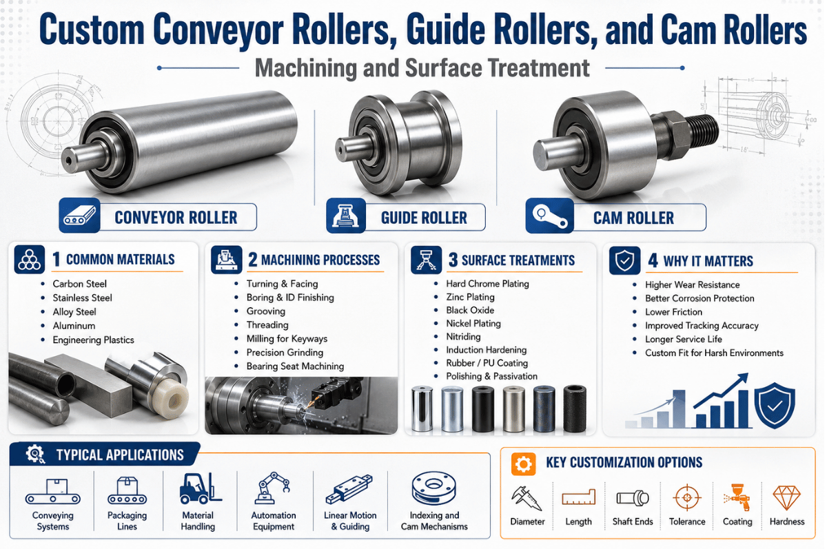
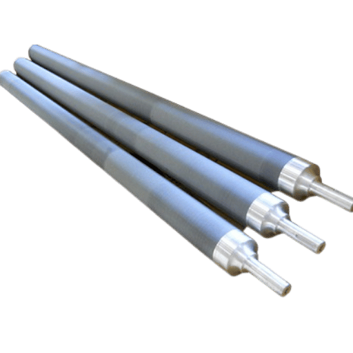
Roller machining covers a surprisingly wide family of parts. A conveyor roller in a warehouse, a guide roller on a slitting line, and a cam follower inside a packaging machine are all turned, ground, and surface-treated cylinders, yet each one carries a different load, runs at a different speed, and fails in a different way. This guide walks through how all three are made, what tolerances and surface treatments actually matter, and where the industry is heading as hard chrome comes under regulatory pressure.
Quick answer: Roller machining is the turning, grinding, and finishing of cylindrical rollers, conveyor rollers, guide rollers, and cam followers, to controlled diameter, concentricity, and surface-finish targets, usually followed by a surface treatment such as hard chrome, nitriding, or a tungsten-carbide thermal-spray coating. The right process depend on the roller’s duty, not on one default recipe.
| Roller families covered | Conveyor (idler / drive / gravity), Guide (V-groove / flat / flanged), Cam follower (stud / yoke) |
| Typical materials | 1045 / 4140 / 4150 steel, 304 / 316 stainless, 52100 bearing steel, cast iron, aluminum |
| Diameter range | ~10–600 mm OD (process-dependent) |
| Best tolerance | ±0.005 mm (Le Creator capability) |
| Concentricity / runout | down to ~5 µm TIR on precision rollers |
| Surface finish | Ra 0.1–0.8 µm (ground / superfinished) |
| Surface treatments | Hard chrome, nitriding, HVOF tungsten carbide, electroless nickel, black oxide, PU / rubber cover |
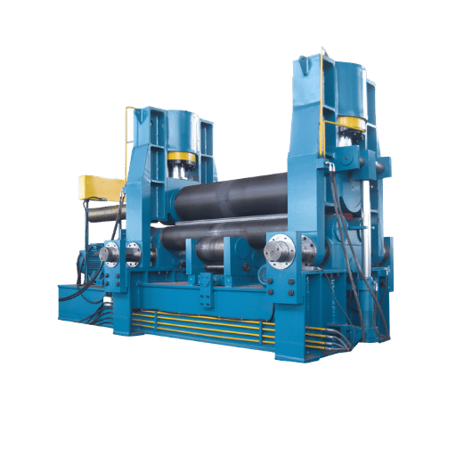
“Roller machining” trips up search engines because the word roller points two ways. One meaning is the rolling mill or plate-bending machine that forms sheet metal. The other, the subject of this guide, is the precision-machined cylindrical componenta staple of the metalworking shop, that rolls, guides, or follows a cam. We’re talking about the second kind: parts you bolt into a conveyor frame, a slitter, or a cam mechanism.
Three families cover most of the demand. Conveyor rollers move product. Guide rollers keep a belt, web, or wire tracking straight. Cam followers (also called cam rollers or track rollers) ride a cam profile or rail and turn rotary motion into precise linear motion. They share a cylindrical body but diverge sharply in how they’re machined and finished.
The three roller types are conveyor rollers, guide rollers, and cam followers. Conveyor rollers are tube-and-shaft assemblies that carry and move loads. Guide rollers are profiled wheels, often V-grooved or flanged, that constrain a moving belt or wire. Cam followers are heavy-duty stud or yoke bearings with a thick, crowned outer ring that rides directly on a cam or track.
This profile maps how conveyor, guide, and cam rollers diverge across twelve machining and finishing attributes, the one-table view no single-product page offers.
| Attribute | Conveyor roller | Guide roller | Cam follower |
|---|---|---|---|
| Primary function | Carry / move load | Constrain / track | Follow cam, carry shock |
| Typical material | 1045 / mild steel tube, stainless | 4140, stainless, nylon / UHMW | 52100 / case-hardened alloy |
| Blank preparation | Tube cut-off, chamfer | Bar saw-cut to length | Bar / forging blank |
| Key turned features | OD, bore, bearing seats | V-groove / flange / crown | Crowned OD, stud, thread |
| Bore / bearing seat | Press-fit housing both ends | Single bore or sealed bearing | Integral needle-bearing seat |
| Grinding need | Light — balance over finish | Profile-dependent | Heavy — OD ground + lapped |
| Tolerance grade | IT8–IT9 | IT7–IT8 | IT5–IT6 |
| Surface finish (Ra) | 0.8–1.6 µm | 0.4–0.8 µm | 0.1–0.4 µm |
| Common surface treatment | Zinc, PU / rubber cover, chrome | Hard chrome, nitride, anodize | Through / case hardening |
| Balancing | Dynamic at belt speed | Usually not required | Not applicable |
| Dominant failure mode | Bearing wear, out-of-round | Groove wear, mistracking | Spalling, brinelling |
| Typical industry | Logistics, food, mining | Converting, steel, wire | Packaging, automation |
Tolerance grades follow ISO 286-1:2010; surface-finish bands are typical machining-shop values.
If you only remember one thing: a conveyor roller is a balancing problem, a guide roller is a profile problem, and a cam follower is a contact-stress problem. That single distinction drive every machining choice that follows, and it’s why a one-size CNC quote rarely fits all three. Most of this work run through a custom CNC machining service rather than an off-the-shelf catalog.
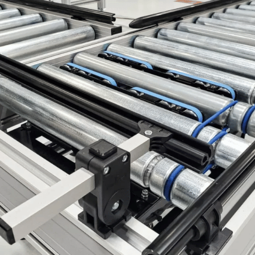
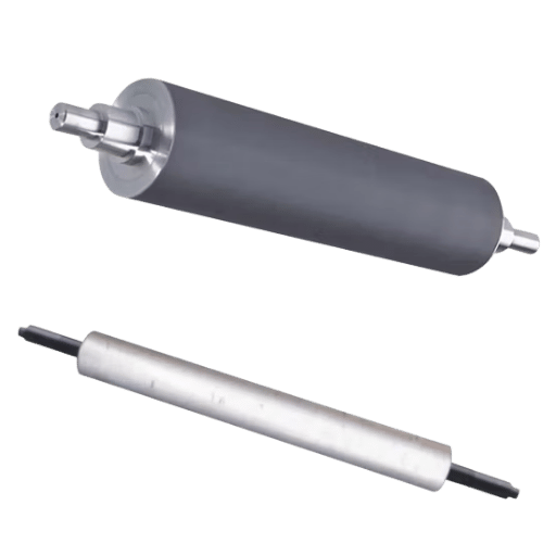
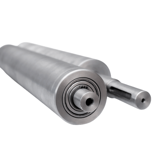
A conveyor roller look simple, a tube spinning on a shaft, but running quietly under load is harder than it appears. Conveyor rollers are machined as a tube-and-shaft assembly: a steel or stainless tube is cut to length and chamfered, bearing housings are pressed or welded into each end, and a shaft is turned to fit the housing bores. The make-or-break feature is concentricity between the bearing bore and the tube’s outer surface.
On fabricated designs the tube is welded to end caps, and the shaft often carries a drilled and tapped end for a retaining bolt. When that concentricity drifts, the symptom shows up at speed: the roller develops a measurable runout, the load thumps once per revolution, and on a powered line the belt start to wander toward the high side. Drive rollers add another constraint, they often need a knurled, rubber-lagged, or polyurethane-covered surface for grip, so the machining sequence has to leave stock for that covering. Gravity and idler rollers, by contrast, are optimized for low rolling resistance, which means the bearing fit and seal drag matter more than the surface itself. For bulk-handling idlers, industry standards such as CEMA 502 standardize roll diameters, bearing sizes, and load ratings, so a “custom” conveyor roller often means matching a defined CEMA class and shaft/bearing fit rather than inventing geometry from scratch.
📐 Engineering Note
For belt speeds above ~2 m/s, specify dynamic balancing and hold bore-to-OD concentricity tight (think IT8 on the housing bore). Below ~1 m/s on a gravity line, that spend is wasted, bearing quality and seal friction govern the feel, not balance.
Scenario: A regional distribution center kept replacing the bearings on one zone of gravity conveyor every few months. The rollers weren’t failing on the bearing, they were slightly out-of-round tubes whose seam had never been machined true, so every revolution shock-loaded the bearing. Re-machining the bore concentric to the tube fixed both the noise and the bearing life in a single pass. The takeaway: on conveyor rollers, the bearing usually pay for a machining error somewhere else.
This tube-and-shaft logic carries straight over to other long cylindrical parts. The same fixturing and concentricity discipline used here’s what a shop relies on for precision shaft machining, where runout drives bearing and gear life.
Guide rollers are machined to stay on a profile. A V-groove guide roller running on a wire or rail lives or dies by two things: the accuracy of the groove angle and the hardness of the running surface. The groove is single-point turned, or form-ground for hardened parts, to a defined included angle that must match the mating profile, with the bore and journal held to ISO 286 fit tolerances.
A common included angle is 90° for wire and rail work; if it drifts off, contact collapses to a line and wear a step into the roller. Material choice splits the field. Where the guide rides a clean, low-load web, machined nylon or UHMW rollers run quiet and need no hardening. Where the guide takes side-load against an abrasive steel rail or a moving cable, the roller is turned from 4140 or stainless and surface-hardened so the groove keeps its shape. A common, expensive mistake is under-specifying that hardness: a soft guide roller on an abrasive rail can wear out of profile in weeks, and once the V-angle opens up, tracking accuracy is gone.
Because guide-roller duty varies so widely, from a hand-loaded jig to a high-tension slitter, published hardness and life figures should be treated as starting points. The honest answer is that the right groove angle, hardness, and material depend on the specific rail, tension, and contamination in your line; a sample part run on your actual rail beats any generic table. Flanged track rollers follow the same rules, just with the guiding surface moved to the flange face instead of a groove.
Here’s the assumption worth retiring: a cam follower isn’t “just a bearing you buy.” It’s a p
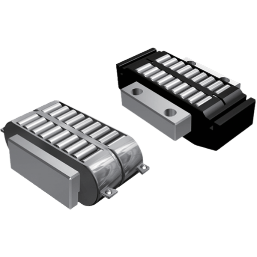
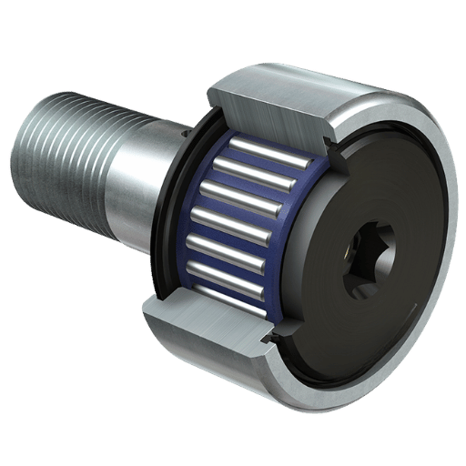
recision-machined component. A cam follower carries a thick outer ring with a crowned (slightly radiused) outer diameter, a stud or hub with a hardened raceway, and an internal needle or roller bearing. The thick ring is what lets it ride directly on a cam or track and absorb the impact that a thin-walled ball bearing couldn’t.
Machining a cam follower is demanding. Its outer ring is turned, then the OD is ground and frequently lapped to a fine finish because it is the rolling surface, there’s no separate race protecting it. The raceway is hardened (52100 or case-hardened alloy steel) and ground true to the bore. The stud is turned and thread-cut for mounting, and on yoke types the mating mounting hole is drilled and sized with a tap. That ground, crowned, hardened outer surface is why cam-follower OD tolerances land at IT5–IT6, far tighter than a conveyor roller.
A stud-type cam follower has an integral threaded stud and mounts from one side, quick to install where you can reach only one face. A yoke-type cam follower has a through-bore and rides a separate clevis pin supported on both sides, so it carries higher loads in double shear with no stud hole reducing the section. Choose stud type for accessibility and lighter loads; choose yoke type when load capacity matters most.
Crown geometry matters more than most buyers expect. A crowned OD distributes contact and tolerates small misalignment between the follower and its track; a perfectly cylindrical follower on a slightly skewed track concentrates load on one edge and brinells early. The decision to crown, and by how much, is a machining specification, not an afterthought. Recent patents confirm how engineered these parts are, from oscillating cam-roller assemblies (US 11,969,988 B2, 2024) to multi-row cam-follower bearings. Many of these followers begin life on the same turning centers used for CNC turning of round parts.
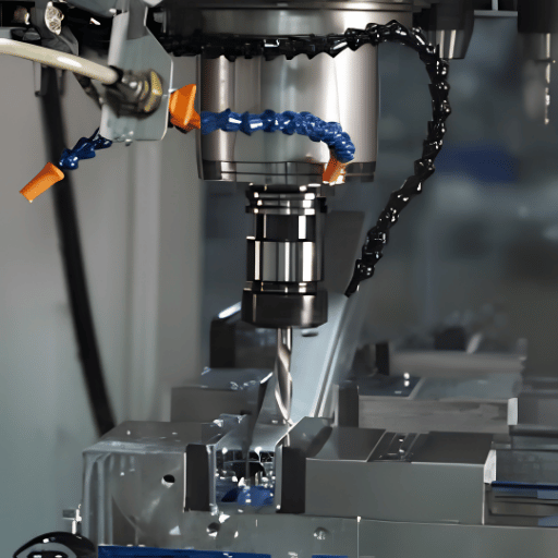
Every roller start on a lathe. CNC turning establishes the diameters, faces, bores, and any threads or grooves, and for many conveyor and guide rollers that’s enough, a turned-and-balanced roller meet the duty. Turning typically lands around IT7–IT9 with a surface finish near Ra 1.6 µm, which is fine for a tube riding on its own bearings but not for a rolling contact surface.
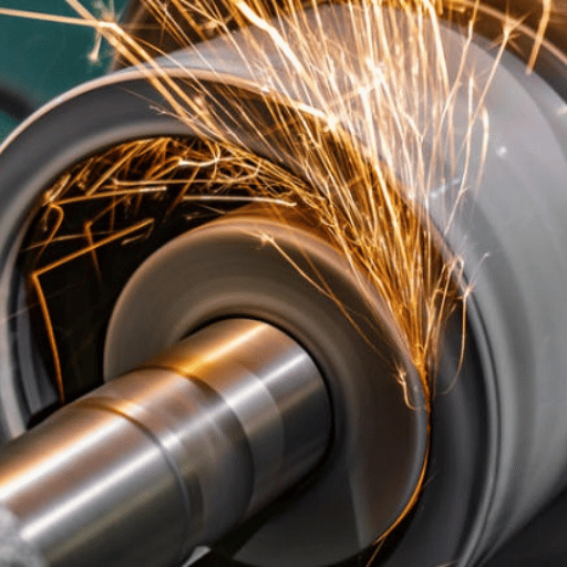
When the OD itself is the working surface, a cam follower, a precision idler, a ground roller for a printing or coating line, grinding takes over. Two routes compete:
✔ Cylindrical (between-centers) grinding
⚠️ Centerless grinding
Peer-reviewed sources line up here: centerless grinding is a fast, efficient process for precision batch and mass production, while between-centers cylindrical grinding gives the tighter mechanically-defined size on a single part. A machinist on Practical Machinist put the trade-off plainly, centerless can offer better surface finishes but a touch less control of size than cylindrical between centers. For a final mirror finish, OD grinding is followed by superfinishing or honing. Cored or hollow rollers add deep-hole drilling, and milled flats or keyways come off a CNC milling setup. Small, slender precision rollers often run on Swiss CNC machining for support against deflection.
If the OD is a bearing-mounted surface → turn only. If the OD is the rolling contact → grind. High volume → centerless. Tightest single-part size → cylindrical. Mirror finish → add superfinish/hone.
Material selection follows duty. 1045 medium-carbon steel machines easily and suits general conveyor and idler bodies. 4140 alloy steel adds strength and hardenability for guide and drive rollers. 52100 bearing steel, high in carbon and chromium, resists fatigue under heavy, high-cycle contact, which is why cam-follower raceways are built from it. Stainless (304/316) handles washdown and food duty at the cost of machinability, and hydraulic-cylinder-rod rollers borrow the same hard-surfaced, corrosion-resistant logic.
Hardening converts a machinable blank into a wear surface. Through-hardening suits small bearing rollers; induction or case (carburizing) hardening puts a hard skin on a tough core where you need surface durability without making the whole part brittle. The hardness target is a contact-stress decision, not a “harder is better” reflex.
Runout tolerance should track the roller’s duty, not the tightest number the shop can hit. These bands set a realistic window by roller class.
| Roller class | Typical runout (TIR) | Process to reach it |
|---|---|---|
| Precision motion (cam follower, metering) | ~2–5 µm | Grind + lap / superfinish |
| Quality web / coating roller | ~5–15 µm | Cylindrical / centerless grind |
| Powered conveyor / drive | ~15–30 µm | Turn + dynamic balance |
| Bulk gravity / idler | ~20–50 µm | Turn to bearing fit |
Diameter tolerance follows ISO 286 IT grades: turning reaches roughly IT7–IT9, grinding tightens that to IT5–IT6 and down toward ±0.005 mm on capable equipment. The practical point, reinforced by the runout window above, is that over-tolerancing a bulk idler to cam-follower numbers buys nothing but cost. This same tolerance-to-process logic shows up in motor shaft machining, where journals are ground while non-critical diameters are simply turned.
Surface treatment is where roller machining gets interesting, because the “obvious” answer is changing. For decades the default was hard chrome. It’s still common, but it’s no longer automatic, and choosing it by reflex can be both a technical and a regulatory mistake.
Neither is universally better, they solve different problems. Hard chrome adds a hard, corrosion-resistant plated layer and rebuilds worn diameters, which suits hydraulic-rod and wear-surface rollers. Nitriding hardens the existing surface by diffusing nitrogen, adding almost no thickness and very little distortion, which suits rollers that must hold tight dimensions. For severe abrasion, a tungsten-carbide thermal-spray coating now outperforms both. Match the treatment to the dominant failure mode: corrosion, fatigue, abrasion, or grip.
Ten treatments span the realistic menu for machined rollers, from plated chrome to elastomer covers, with the hardness and thickness that separate them.
| Treatment type | Layer thickness | Surface hardness | Best for |
|---|---|---|---|
| Hard chrome (ASTM B650) | 2.5–25 µm (Cl.1), >25 µm (Cl.2) | ~800–1000 HV | Wear + corrosion, rebuild |
| Thin dense chrome | 2–8 µm | ~850–1000 HV | Tight-tolerance wear surfaces |
| HVOF tungsten carbide | 100–300 µm | ~1000–1300 HV | Severe abrasion, chrome replacement |
| Electroless nickel | 5–50 µm | ~500–700 HV (heat-treatable higher) | Uniform corrosion resistance |
| Gas / plasma nitriding | case ~0.1–0.5 mm (diffusion) | ~900–1100 HV (nitriding steel) | Fatigue + dimensional stability |
| Induction / case hardening | case 0.5–3 mm | ~55–62 HRC | Tough core + hard skin |
| Ceramic (chrome oxide) spray | 100–300 µm | ~1100–1400 HV | Web grip, anilox, high wear |
| Black oxide | <1 µm | base hardness | Mild corrosion, low glare |
| Polyurethane cover | 2–25 mm | ~60–95 Shore A | Grip, quiet, gentle handling |
| Rubber cover | 3–25 mm | ~40–90 Shore A | Drive traction, low marking |
Hardness/thickness are typical published ranges; hard-chrome thickness classes per ASTM B650 and NASA PRC-5003.
Hard chrome on an impact-loaded surface. Hard chrome carries an inherent micro-crack network, the same structure that makes it hard makes it prone to spall and peel under shock or when plated too thick. Failure analyses of chrome-plated rods trace peeling to those micro-cracks and pores. On a cam follower that hammers a cam lobe, that’s exactly the wrong property; case hardening or a thermal-spray carbide hold up better. Properly processed chrome does manage that crack network, a post-plate hydrogen bakeout relieves embrittlement and shot peening adds compressive stress that resists crack propagation. The failures show up when chrome is run too thick, skips those steps, or sits on a shock-loaded surface.
Abrasion data favors the newer coatings. Reman and coating-industry comparisons report that HVOF and HVAF tungsten-carbide coatings are markedly harder than hard chrome and lose far less volume in standardized abrasion testing, and peer-reviewed work has shown WC-CoCr HVOF outperforming hard chrome on AISI 1045 hydraulic rods. That performance edge, combined with the regulatory pressure covered next, is steering high-wear roller surfaces away from chrome. One caveat keep chrome and electroless nickel firmly in the game: thermal spray is a line-of-sight process, so it coats outer diameters well but struggles on internal bores, small diameters, and shielded surfaces, exactly where plating still wins.
The fastest way to a roller that work, and a quote that means something, is to hand the shop the right information up front. A drawing with GD&T, the material, the tolerance and surface-finish targets, the surface treatment, the quantity, and any certification requirement turns a guessing game into a build.
Four questions move a roller from “we think we need” to a buildable specification.
A capable shop should answer back with a first-article plan and a material certificate, not just a price. Le Creator machines rollers across all three families under ISO 9001:2015, IATF 16949, AS9100D, and ISO 13485 quality systems, holds tolerances to ±0.005 mm, and has delivered 50,000+ custom projects at a 98.5% on-time rate, the kind of traceable, multi-process capability a one-line catalog roller cannot match. The point of the four questions is to make sure the part is specified before it is priced.
The biggest shift in roller machining for 2026 is not on the lathe, it is in the plating shop. Hexavalent chromium, the chemistry behind hard chrome, is squarely in the regulatory crosshairs. Under the EU REACH regulation, chromium trioxide sits on Annex XIV with a sunset date that already passed (21 September 2017), meaning its use now requires specific authorisation. In the United States the pressure is about exposure control rather than an outright ban: OSHA caps worker exposure at a permissible exposure limit of 5 µg/m³ (8-hour TWA), so hard chrome stays usable where a shop meets those controls, but compliance cost keeps climbing. Germany’s Federal Environment Agency notes that hard chromium’s hardness can only be reached with heat treatment that is “not always possible,” and points to nickel-alloy deposition among the alternatives.
That regulatory pressure lines up with the technology trend: tungsten-carbide thermal spray, thin-dense chrome, and electroless nickel are taking over the rollers that hard chrome used to own. Patent activity reflects it, from chrome-free arc-spray coating chemistries to cermet-coated rolls. Market growth, meanwhile, stays steady: industry analysts put the industrial-coatings market in the low hundreds of billions of dollars in 2025 with mid-single-digit annual growth, and the thermal-spray-coatings segment specifically is forecast to grow around 6% per year through the early 2030s, with sustainability and chrome alternatives named as the fastest-moving themes.
What to do in 2026: if you run or buy chrome-plated rollers, especially anything sourced into or out of the EU, audit them now for a substitution path. Identify which rollers truly need chrome’s specific properties and which can move to HVOF carbide, electroless nickel, or nitriding before authorisation pressure tightens or a supplier drop the line. Re-specifying on your schedule is cheaper than re-specifying on a regulator’s.
“The hardness of hard chromium layers can only be achieved by heat treatment, which is not always possible” — which is exactly why nickel-alloy and thermal-spray coatings keep gaining ground for engineered roller surfaces.
This guide consolidates roller machining and surface-treatment practice across conveyor, guide, and cam-follower parts, drawing on standards (ISO 286, ASTM B650), government exposure and substitution data (OSHA, NASA, the German Federal Environment Agency), and our own shop experience machining and grinding precision rollers to ±0.005 mm. Hardness, thickness, and tolerance figures are typical published ranges; your results vary with material, geometry, and equipment, so we recommend a sample part on your actual application.