Supportive, Professional, Client-Focused Service
Get in touch with Lecreator Company
From prototypes to full-scale production, we’ve got you covered.


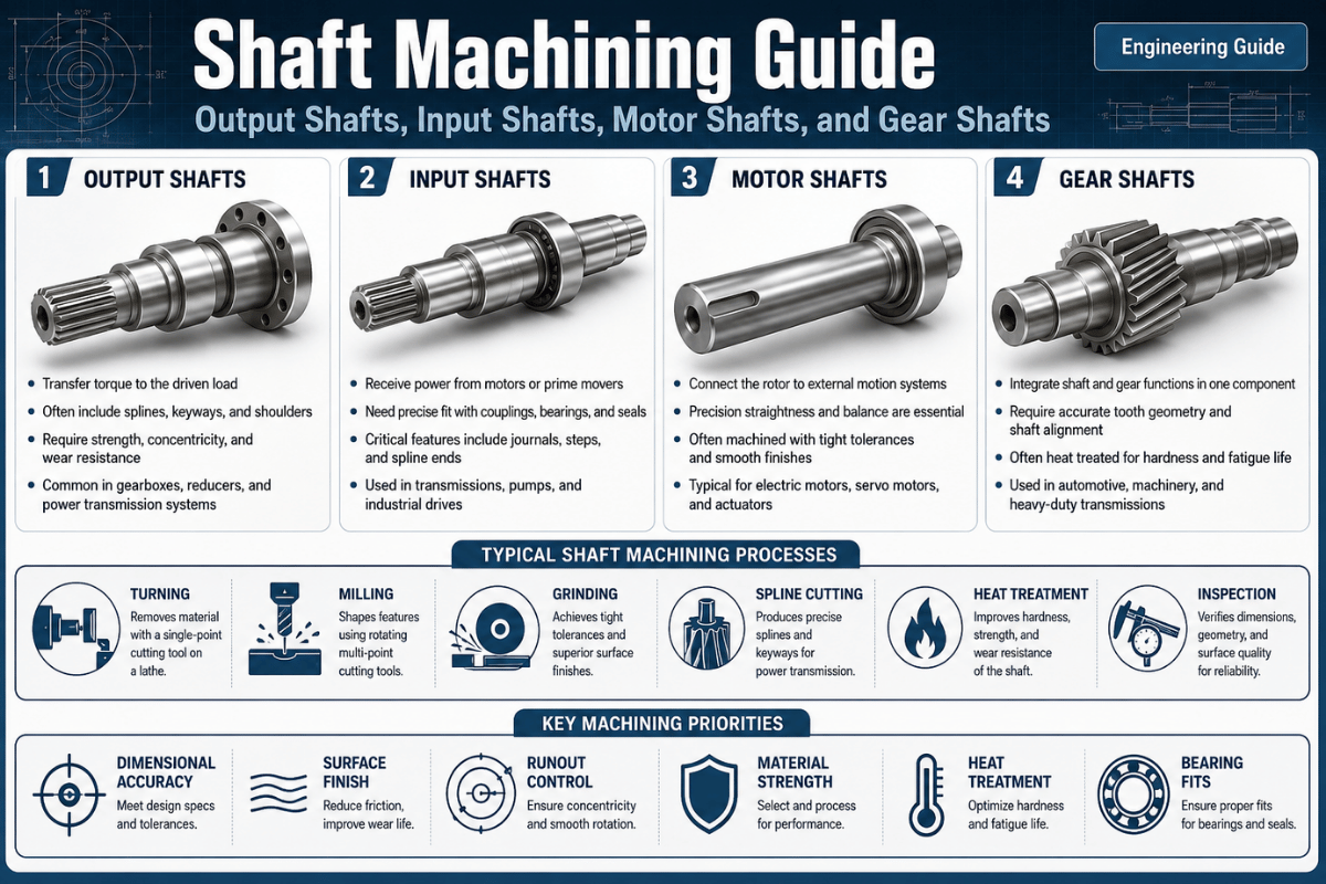
Shaft machining is the precision machining process that turns plain bar stock into the rotating shafts on which every gearbox, motor, and pump relies. Whether you’re ordering an output shaft for a reducer, an input shaft for a transmission, a motor shaft, or a gear shaft, how it’s turned, milled, heat-treated and ground dictates whether it spins true for years or eats bearings in months. This article steps through the four critical shaft types, the 5-stage process route, hard-numbers material selection, tolerances, and the design and sourcing approach that actually fit.
Put another way: shaft machining makes cylindrical rotating parts, turning sets the diameters and concentricity, milling and broaching create keyways and splines, heat treatment gives the required hardness, and grinding sizes and finishes the bearing journals. Production shafts hold diameter tolerances down to ±0.005 mm and bearing-journal concentricity within 0.005–0.02 mm TIR, with cost driven largely by material choice and the length-to-diameter ratio.
| Typical diameter range | 1–500 mm (Swiss micromachining from 0.5 mm) |
| Achievable diameter tolerance | to ±0.005 mm (ground) |
| Journal concentricity | 0.005–0.02 mm TIR (ISO 1101 runout) |
| Surface finish | to Ra 0.2 µm on ground journals |
| Common materials | 1045, 4140, 4340, 8620, 304/316, 17-4PH |
| Core processes | CNC turning, milling, drilling, grinding |
Shaft Machining is the subtractive process of turning, milling, drilling and grinding cylindrical bar stock into a precisely rotating shaft that transmits torque and motion between machine components — the defining function set out in machine-design texts such as Shigley’s Shafts and Shaft Components.
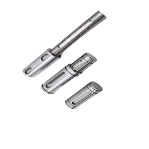
A raw bar of metal by itself is useless- machining provides the stepped diameters, bearing seats, keyways and threads that allow it to support a gear, accept a bearing and spin true under power. As a branch of precision CNC manufacturing, shaft machining produces every type of shaft, from a plain round bar to a splined gear shaft; the broader term shaft manufacturing also covers forming the blank.
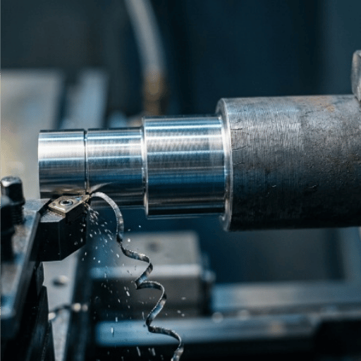
Turning on the lathe does most of the work in the procedure by holding the part rotate and setting each diameter using a single point cutting tool from a common concentric datum. Milling then adds features like keyways, flatting and slots. Drilling, adding thru-holes or counterbores, and grinding are the final operations completing the critical journals to tolerance. By machining a shaft using a turning first method as opposed to a milling-first strategy, all other features remain on center. This is exactly what’s required of a machined shaft.
Why is precision so important? A bearing journal 0.002 mm under size and the bearing spins freely and over-heats; 0.002 mm oversized and the bearing fractures when pressed in place. At high speed, any lack of concentricity is an unbalanced mass, beating seals loose and pounding bearing journals. You have to control diameter, concentricity, and surface finish together, not one at a time.
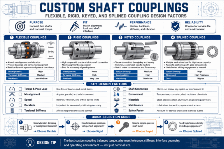
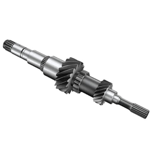
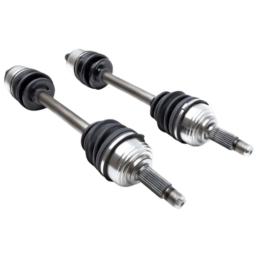
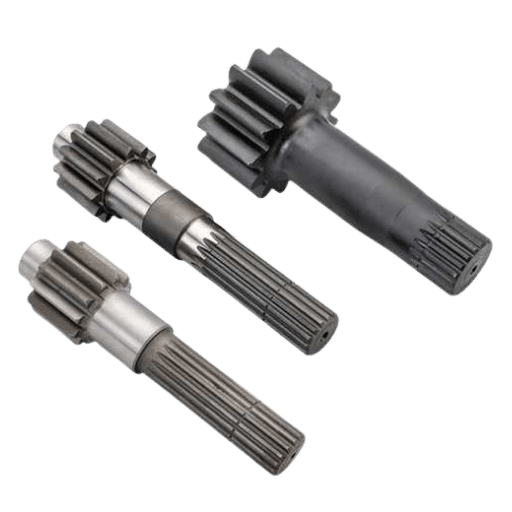
An input shaft serves as a powered starter to a component set, an output shaft transmits the work being performed, a motor shaft is integrated with a motor’s rotating part and a gear shaft has cut or pressed on gears, as defined. Each type imposes different concentricity requirements, journal tolerancing, and splining needs — a load-and-function distinction echoed in WPI’s machine-design notes — so identifying a shaft by what it does versus just how it’s shaped is key to narrowing down the scope of required machining, which this chart below will identify and organize via the Output-Input-Motor-Gear Shaft Function Map to categorize the full range of shafts engineers usually require.
| Shaft type | Primary function | Key machined features | Dominant tolerance driver |
|---|---|---|---|
| Output shaft | Delivers torque from a gearbox/reducer to the load | Stepped journals, keyway or spline, threaded end | Bearing-fit concentricity + spline/key fit |
| Input shaft | Receives power from the prime mover into a gearbox | Internal/external spline, pilot diameter, seal surface | Spline fit + seal-surface finish |
| Motor shaft | Integral rotor shaft; first point of torque | Rotor-core diameter, keyway/flat, bearing journals | Concentricity & balance (vibration) |
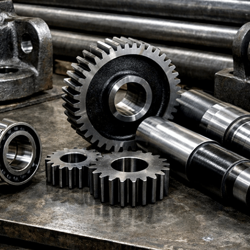
| Gear shaft | Carries cut or mounted gears in a train | Integral gear teeth or spline, shoulders, fillets | Tooth/journal alignment + fatigue at roots |
| Drive shaft | Moves power across distance under cyclic load | Yoke/spline ends, balanced tube or bar | Fatigue + dynamic balance |
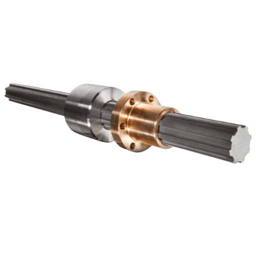
| Spline shaft | High-torque sliding/locking power transfer | Involute or parallel splines | Spline form & pitch tolerance |
| Line shaft / countershaft | Distributes or redirects power between units | Multiple keyways, long bearing journals | Straightness over length |
| Jack shaft | Short intermediate shaft linking two components | Twin journals, keyways | Alignment between mounts |
| Crankshaft | Converts reciprocating to rotary motion | Offset pins, oil holes, large fillets | Fillet fatigue + journal grind |
| Camshaft | Times valve/actuator motion | Profiled lobes, bearing journals | Lobe profile + hardness |
| Hollow shaft | Cuts mass, raises stiffness-to-weight | Bored or gun-drilled bore, wall control | Wall concentricity |
The bottom line: a motor shaft live or dies on concentricity and balance, an automotive drive shaft on fatigue, and a gear or output shaft on how cleanly its splines and journals share one axis. Don’t over-engineer it, and don’t overpay for tolerances the job never needed.
A shaft isn’t made off the end of one bar in a single pass, it moves through a step-by-step sequence dictated by geometry (simple vs. stepped vs. slender), material (soft vs. hard), and fit (loose vs. tight tolerance). The route common to most precision shafts follows the pattern below, the 5-Stage Shaft Process Route:
| Stage | What happens | Why it matters |
|---|---|---|
| 1. Rough turning | Face, center-drill, and rough each diameter between centers | Removes bulk material; sets the working centerline |
| 2. Finish turning | Bring diameters, shoulders, chamfers, and fillets to near-net size | Establishes geometry and concentricity in one setup |
| 3. Feature machining | Mill keyways/flats, hob or broach splines, drill holes, cut threads | Adds torque-transfer and assembly features |
| 4. Heat treatment | Through-harden, case-harden, or induction-harden, then temper | Builds strength and wear resistance—but distorts the part |
| 5. Grinding / finishing | Cylindrical or centerless grind bearing journals to final size | Recovers tolerance lost to heat treat; sets surface finish |
There’s a reason shafts are machined soft, hardened, then ground last: heat treatment shifts dimensions. The U.S. metallurgical reference Failures of Shafts from ASM International lists quench cracks and heat-treat distortion among the most common shaft fabrication defects. The finish-grind step exists largely to correct that distortion, not only to polish the surface, skip it on a hardened journal and the bearing fit drifts out of tolerance.
Take a stepped shaft with two bearing journals and a keyed output end. The bar, chosen slightly larger than the biggest diameter, is clamped in a collet on a CNC turning center, faced, and center-drilled. The largest diameter is rough-turned first, working down to the smaller steps so the part stays rigid; finishing passes then form clean shoulders and fillets.
The shaft moves to a mill for the keyway, gets heat-treated if the duty demand it, and finally has its journals ground to size and checked for runout on a CMM before it ships. Multi-axis turn-mill machining can combine several of these steps in one clamping, which improves concentricity by removing re-fixturing error.
Not always. Trade sources such as Production Machining document hard turning and rotational turning replacing the grinding op on many hardened journals when the tolerance and finish allow, and Engine Builder notes it’s “not always necessary to grind a crankshaft” back to spec. CBN hard turning can reach bearing-grade finishes in a single chucking, often cutting cost, though Modern Machine Shop still finds grinding wins for the tightest roundness and the hardest stock. The choice is fit-driven, not automatic.
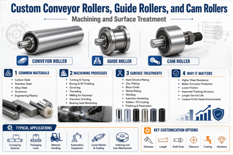
Material sets the baseline for strength, fatigue life, corrosion resistance, and machinability, and most competing guides stop at “carbon steel is cheap, alloy steel is strong.” The Shaft Material-to-Duty Selector below puts numbers behind the choice. (Values are typical quenched-and-tempered properties for the named grades; confirm against your supplier’s certified mill values.)
| Material | Tensile (MPa) | Yield (MPa) | Machinability | Best-fit shaft duty |
|---|---|---|---|---|
| 1045 carbon steel | ~565 | ~310 | Good | General-purpose, low-load shafts |
| 4140 alloy steel | 850–1000 | 655–900 | Moderate | Workhorse drive/output shafts |
| 4340 alloy steel | 1000–1200+ | 740–1050 | Harder | High-torque, high-fatigue shafts |
| 8620 case-harden steel | ~530–700 | ~360–500 | Good | Gear/spline shafts (hard case, tough core) |
| 304 stainless | ~515 | ~205 | Gummy | Mild-corrosion service |
| 316 stainless | ~515 | ~205 | Gummy | Marine, food, chemical shafts |
| 17-4PH stainless | ~1070–1310 | ~1000–1170 | Moderate | High-strength corrosion-resistant shafts |
| Ti-6Al-4V titanium | ~950–1100 | ~880–1000 | Difficult | Aerospace, medical, weight-critical |
| 7075-T6 aluminum | ~572 | ~503 | Excellent | High-speed, low-load light shafts |
| Brass C360 | ~340–470 | ~125–310 | Excellent | Small precision/instrument shafts |
For most high-torque drives and output shafts the answer is 4140 or 4340. AISI 4140 reaches 655–900 MPa yield after quench and temper, machines more easily, and can be induction-hardened for a wear-resistant journal, it’s the default for most industrial power shafts.
AISI 4340 adds nickel for extrahigh core toughness (yield about 740-1050 MPa and well beyond with specialized treatment), which makes it worth the premium and hard machining on the most fatigue-critical, shock-loaded shafts; though it costs more and wears away the cutters faster. If corrosion is also a concern, 17-4PH achieves near-alloy steel strength with stainless qualities. Match the grade to the duty rather than overspecify: a 1045 shaft that gets the job done is better than a 4340 shaft that bills for strength the application never allows.
Lecreator machines all of these in-house, from stainless steel shaft stock to titanium and the carbon and alloy steels that make up most production shafts.
Features are precisely where a round bar turn into a functioning shaft-and where it most often proves to be a weak point. Keyways, splines, shoulders, and grooves will transfer torque in and through them, but are stress-concentration sites that can initiate fatigue cracks in rotating shafts. A finite-element study of stress concentration factors in shaft keyways confirms that localized geometric stress raisers dominate fatigue design, so how a feature is machined matters as much as that it exists.
| Feature | Process | Fatigue / quality watch-point |
|---|---|---|
| Keyway | End-mill or broach | Radius the corners—sharp keyway ends are crack origins |
| External spline | Hobbing, milling, or thread-style rolling | Form/pitch tolerance; rolling adds fatigue strength |
| Internal spline | Broaching or shaping | Tooth alignment to bore axis |
| Thread | Single-point turning or thread rolling | Never carry torque on threads; roll for fatigue life |
| Gear teeth | Gear hobbing | Root fillet + tooth-to-journal concentricity |
| Features on hardened stock | Wire EDM | No cutting force or heat-affected distortion |
Keyways are usually cut with an end milling on a CNC mill for small quantities or broached for mass production, and tolerated according to ANSI B17.1 (inch) or ISO/DIN key standards. Splines are milled or shaped by hobbing for cut teeth, or formed cold working instead of cutting;This cold-working creates work hardening on the flanks, leading to higher fatigue strength.
On fullyhardened shafts-where milling or hobbing would develop chatter or burn-wire EDM cuts the keyway or spline without any mechanical force. Of all these options, the place where the most attention and focus should be directed is the internal radius: a sharp internal corner magnifies the local stress and is the classic location for a loaded shaft to break.
Concentricity between bearing journals on a machined shaft is usually held to 0.005–0.02 mm TIR, and once a shaft’s length-to-diameter (L/D) ratio climbs past roughly 10:1, the exact point depends on material stiffness and the tolerance demanded, deflection forces the use of a steady rest or machining between centers to hold size. Two different standards govern these numbers, and conflating them is a common mistake: ISO 286 covers diameter sizes and fits (the h6/g6/k6 classes on a journal), while form and runout, concentricity, total runout, straightness, belong to the GD&T family ISO 1101. Call out a journal as “Ø20 g6” for the fit and a runout symbol for the spin, not one in place of the other.
| L/D ratio | Workholding strategy | Practical outcome |
|---|---|---|
| Up to ~8:1 | Chuck (cantilever) turning | Rigid; tight tolerance straightforward |
| ~8:1 to 20:1 | Between centers + steady/follow rest | Controls deflection & chatter; “challenging” |
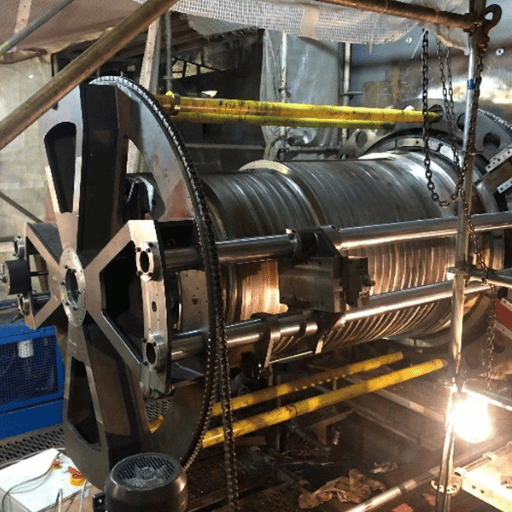
| >30:1 (extra-long) | Between centers, multiple rests, reduced feeds | Lead screws, mill rollers; finish-grind for straightness |
A slender shaft acts like a floppy ruler: the push of the cut forces it away from the tool, so it becomes fat in the center and tapers to the ends. Adding a steady rest put a contact point partway down the shaft (a follow rest contacts the tool); it shortens the unsupported span, reducing deflection.
Machinists on Practical Machinist explain using steady rests on precisely turned surfaces, to control shaft overhang and L/D. Even better: heating during long machining cycles will expand the part’s center; this expansion and shafts’ critical speeds on high-speed motors, pumps and spindles limit how slim the design can be before vibration.
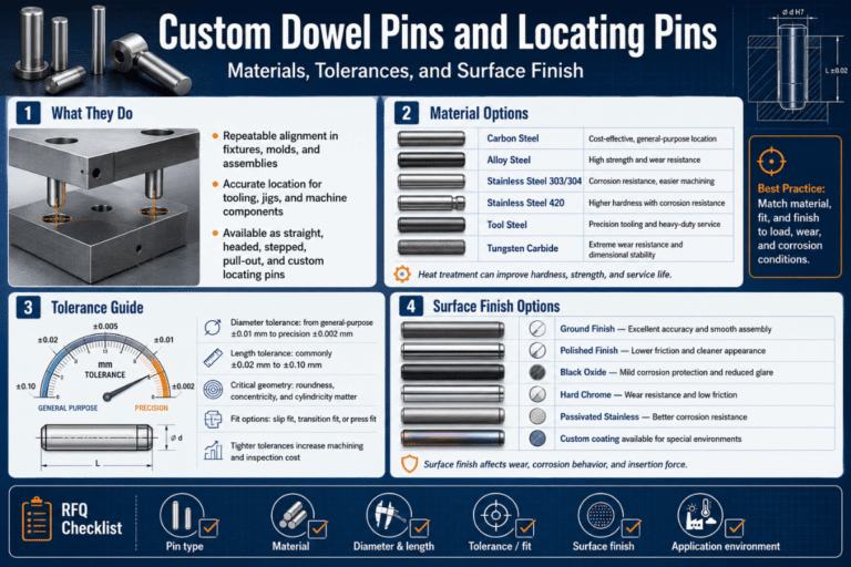
Don’t strive for impossible perfection. Giving every diameter tighter tolerances inflates inspection and grinding times but has no practical effect. Sub-0.01mm tolerances should be reserved for bearings and seals; non-critical lengths may use the more common ISO 2768 tolerances. Generally, cylindrical-grinding tolerances on a diameter run about ±1–10 µm, with surface finishes down to roughly Ra 0.2 µm, at an ever-escalating cost.
Good shaft design cuts the cost and time you spend at the lathe. The classic method, laid out in Shigley’s Shafts and Shaft Components and historically codified in ANSI/ASME B106.1M (the 1985 transmission-shafting standard, now withdrawn but still widely referenced) — sizes the shaft from the loads and fatigue stresses it must survive. The key principles:
For the authority behind these rules, the Worcester Polytechnic Institute machine-design notes and the failure-mode survey from City University of Hong Kong both trace shaft failures back to geometry and heat-treatment decisions made at the design stage.
Heat treatment and finishing are where a shaft earns its hardness, wear life, and final tolerance. The sequence almost always reads machine soft → heat-treat → grind hard, because hardening distorts the part and grinding restores size afterward.
| Process | Result | When to use |
|---|---|---|
| Induction hardening | Hard case ~50–60 HRC, tough core | Bearing journals, gear-shaft teeth |
| Case hardening (carburize) | Wear-resistant skin on tough core | 8620 gear/spline shafts |
| Through hardening + temper | Uniform strength through section | 4140/4340 power shafts |
| Nitriding | Very hard surface, low distortion | Precision shafts that can’t be re-ground much |
| Cylindrical / centerless grinding | ±1–10 µm size, Ra to ~0.2 µm | Final journal size and finish |
| Hard chrome / TG&P stock | Wear + corrosion surface; precise stock | Hydraulic rods, linear shafts |
“We never chase the final size of a hardened journal before heat treat,” explains a machinist from a gear supplier. “We leave plenty of room for grinding after heat treat and run a cylindrical grinder to bring it back. Trying to hold your tolerances at the soft stage and keep it that way through the quench is where parts become scrap.”
Turning & grinding lead, Lecreator
Where a shaft pairs against a precision bore, concentric honing on the bore finishes the fit from the “other side.”
shaft machining price isn’t linear-it increases rapidly as material, length, tolerance, and complexity push beyond “standard turning.” Primary cost drivers are: material grade and heat-treating; L/D ratio and consequent workholding strategy; tolerance, target surface finish band; feature complexity (keyways, splines, cross-holes); inspection requirements; and batch size, which spreads the setup cost over more parts. A bearing-grade ground journal on a 4340 shaft with a 20:1 L/D costs a totally different universe than a plain 1045 rod.
On the factors buyers actually weigh: in our own shaft work, Lecreator holds best-case ground tolerances of ±0.005 mm and a 0.02% defect rate across 50,000+ delivered projects, with 100% inspection on production runs. For overseas sourced work, the landed cost is the metric to use-a typical $5,000 FOB quote arrives in the customer’s possession DDP to their door roughly at the level of a typical $7,425 DDP price when you factor in the 25% Section 301 tariff, freight, and brokerage (roughly a 48.5% markup over FOB, yet still approximately 52% below comparable US machining). Knowing this arithmetic upfront separates price shocks from reliable bids.
Select a shaft supplier based on ability to hold geometry, replicate it and document it-not on the headline “price.” Long, thin parts are unforgiving and reveal weak setups readily (taper, chatter, diameter drift), so inquire about L/D capability and view inspection reports before deciding on your bearing-fit tolerances-not after. A shop with integrated turn-mill operations and guaranteed runout by lot will offer far less costly rework than low-ball quotes for undocumented parts.
Request a Shaft Machining Quote →
Demand for machined shafts follows general trends in precision-turned products with global market size approaching a 6.0-6.4% CAGR up to 2034-2035 per reports from Precedence Research and Market.us (including precision shafts and pins as a product class leader); broader precision manufacturing stands at ~8% as forecast by Grand View Research. On the shop floor, consider these three 2026 technology themes relevant to shafts: AI-driven CAM that adapts paths for slender parts to fight chatter; digital-twin simulations for deflection prediction; and turn-mill consolidation and CBN hard turning to reduce steps, improve concentricity. Practical advice: for 2026 shaft development programs, Design to ISO 1101 GD&T requirements; discuss whether hard turning could eliminate grinding in your tolerance; and use a turn-mill vendor with automated in-process inspections.
When long slender shafts with high length to diameter ratio bend excessively due to cutting force, support it with a steady rest or follow rest instead of trying to “push through”, decrease feed rates and use very sharp cutting tools to minimize force, or add stages of roughing before finish cutting to remove sections gradually, thus supporting more of the shaft.
These supports become necessary beyond L/D of about 10:1. With very high ratios (L/D > 30:1) these become the “extra-long” shaft category where the shaft is typically ground to dimension after heat treatment to correct heat treat distortion. Beyond the machine stage, very long high-speed shafts will also be limited by their critical speed, which is dictated by the tendency of the rotational whirl to take over regardless of precision and turning capability, making deflection a primary factor for the running, rather than static, machine.
Typical turn around for a finished shaft depends on how complicated the dimensions are, if any hardening and Grinding are necessary, and what the production volume. A simple turned shaft may require only a few days, whereas a hardened and ground shaft with multiple features takes more time as heat treating and grinding are added processes.
Lecreator can turn around prototypes in days, with a quotation in under 24 hours, and production shafts available from that timeframe and up.
This guide reflects Lecreator’s day-to-day work turning and grinding output, input, motor, and gear shafts in 1045, 4140, 4340, stainless, and titanium, where we hold best-case ground tolerances of ±0.005 mm with 100% inspection. The tolerance, material, and process figures are cross-checked against machine-design references (Shigley, WPI, ASM International) and current standards (ISO 286, ISO 1101, ASME Y14.5-2018). Reviewed by the Lecreator technical team.