Supportive, Professional, Client-Focused Service
Get in touch with Lecreator Company
From prototypes to full-scale production, we’ve got you covered.


Updated June 2026 · Reviewed by the Le Creator Technology Co., Ltd. technical team
Custom shaft couplings are made-to-print torque-transmitting connectors machined to a specific bore, keyway, length, material, and balance grade rather than pulled from a catalog. Like any shaft coupling, their job is to join two rotating shafts so power passes from a driving shaft to a driven shaft while either holding precise alignment or absorbing the small misalignments that real machinery always has. Every coupling on the market fall into one of two families, rigid or flexible, and almost every selection mistake traces back to confusing the two. This guide walks the six coupling families, the connection methods that grip the shaft, the five design factors that actually decide your choice, and the machining details a custom coupling drawing has to specify.
| Torque to size for | Peak torque × service factor (1.5–3× for shock/reversing loads) |
| Speed / balance trigger | Dynamically balance the coupling once assembly speed pushes the rotor past its ISO 21940-11 grade (commonly G6.3 general, G2.5 high-speed) |
| Misalignment tolerated | Rigid ≈ 0; bellows ≈ up to ~1 mm parallel / ~2° angular; jaw, gear, Oldham, U-joint handle progressively more |
| Bore & connection | Keyed (ASME B17.1 / DIN 6885), keyless friction clamp, splined, set-screw, or D / hex bore |
| Backlash | Zero (clamped rigid, bellows, disc) vs finite (jaw spider, gear, Oldham, set-screw) |
| Typical materials | Steel, stainless steel, aluminum (with black-oxide or passivated finishes) |
A shaft coupling is a mechanical component that connects two collinear or nearly collinear shafts to transmit rotational torque and power while accommodating limited misalignment. That single sentence hides the whole decision: a coupling has to carry torque, and it has to deal with the fact that the two shafts it joins are never perfectly aligned.
Thermal growth, foundation settling, bearing wear, and ordinary assembly tolerance all push shafts out of line over time, and university research on shaft misalignment shows that offset turn directly into bearing load once the shafts rotate.
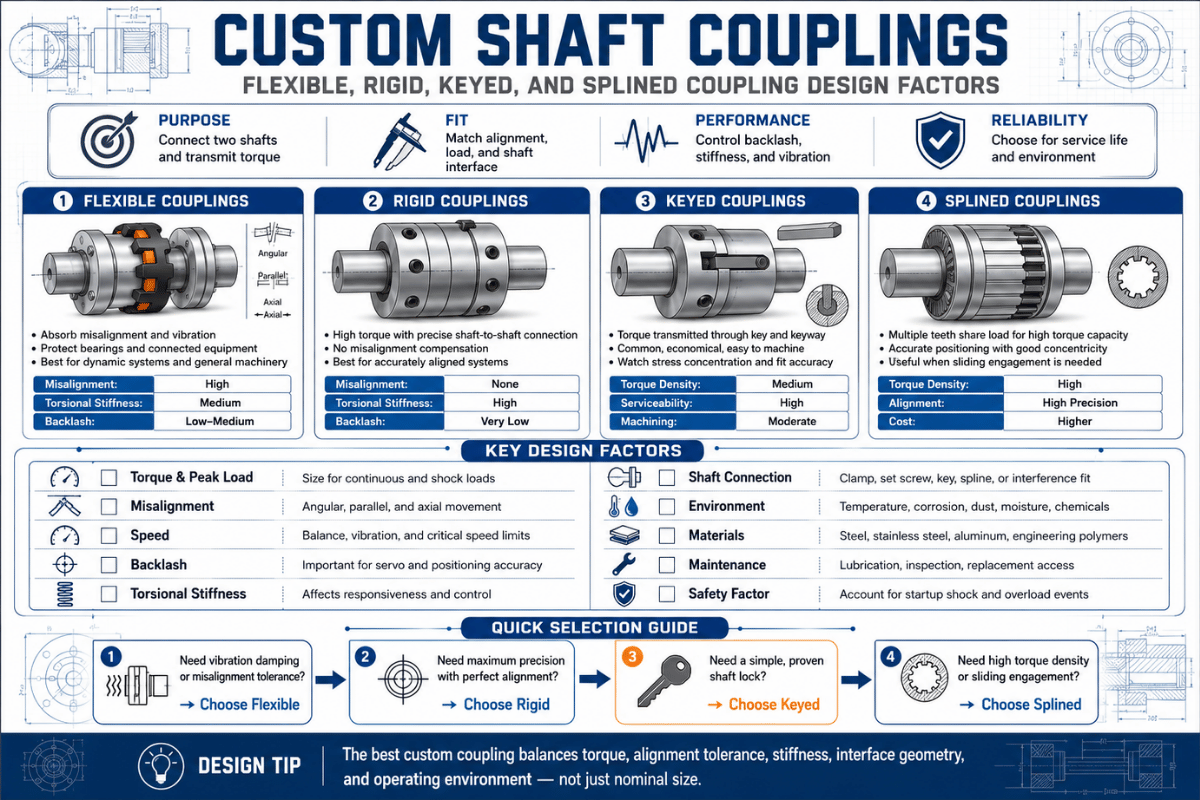
Couplings split into two families. Rigid couplings lock the shafts together with no give, maximum torsional stiffness and zero backlash, but they tolerate almost no misalignment. Flexible couplings add an element, an elastomer, a thin metal disc, gear teeth, a sliding disc, that bends or slides to absorb angular, parallel, and axial offset. Everything else is a variation on those two ideas. (This guide cover mechanical torque-transmitting couplings; fluid/hydrodynamic and magnetic couplings are a separate class and out of scope here.)
Before reading any product page, place your application on a spectrum of six mechanical coupling families. Each trades torque density, misalignment capacity, and backlash against one another, there’s no single “best” coupling, only the right fit for your torque, speed, and alignment reality. Modern one-piece designs such as the patented flexible coupling US5,041,060 combine angular, parallel, and axial capacity in a single body, but each family still sit at a different point on the spectrum.
| Coupling type | Family | Torque density | Misalignment | Backlash | Best for |
|---|---|---|---|---|---|
| Sleeve / muff | Rigid | High | None | Zero | Perfectly aligned, well-supported shafts |
| Clamp / split | Rigid | High | None | Zero | Aligned shafts needing easy on/off without disturbing position |
| Flange | Rigid | Very high | None | Zero | Large-diameter, high-torque line shafts |
| Jaw / spider | Flexible (elastomeric) | Medium | Moderate (all 3) | Finite | Motor→pump, shock and vibration damping, fail-safe drives |
| Tyre / elastomer | Flexible (elastomeric) | Medium | High | High | Heavy shock loads, large misalignment, no lubrication |
| Oldham | Flexible (sliding) | Medium | High parallel | Low/zero | Large parallel offset with low backlash; sacrificial disc protects the drive |
| Beam / helical | Flexible (metallic) | Low | Low–moderate | Zero | Encoders, light motion control, one-piece simplicity |
| Bellows | Flexible (metallic) | Low | ~1 mm / ~2° | Zero | Servo and encoder axes needing high torsional stiffness |
| Disc | Flexible (metallic) | High | Moderate | Zero | High-speed, high-torque precision; no lubrication |
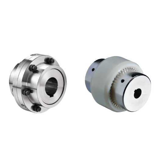
| Gear | Flexible (mechanical) | Very high | Moderate | Finite | Heavy-duty high-torque drives; needs lubrication |
| Grid | Flexible (mechanical) | High | Moderate | Finite | High torque with shock damping; needs lubrication |
| Universal joint | Flexible (mechanical) | Medium | Very high angular | Finite | Large intersecting-shaft angles (pair them to even out velocity) |
Misalignment and backlash bands are typical ranges; confirm against the specific series before you commit. Type taxonomy cross-checked against industry coupling engineering sources.
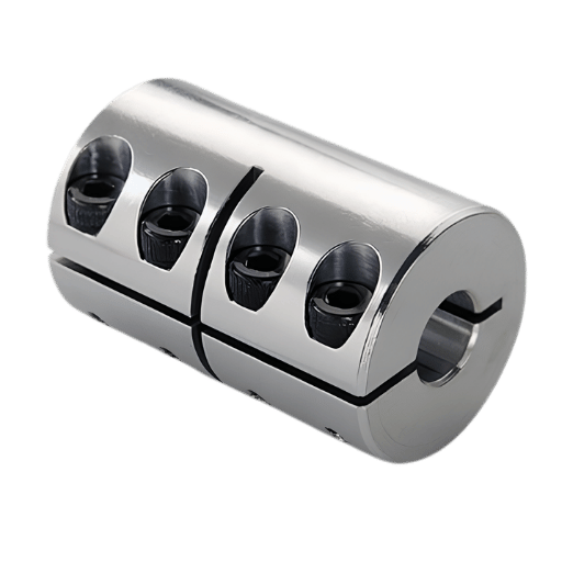
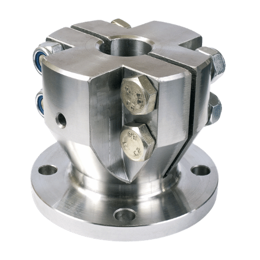
Rigid couplings, sleeve (muff), clamp/split, and flange, lock two shafts into one rotating body. They deliver maximum torque transfer and the highest torsional stiffness with zero backlash, which is exactly what you want when the shafts are genuinely co-axial and when a flexible element would only add lost motion. Typical homes are vertical pump line shafts, sectioned long shafts that need a structural splice, and indexing or positioning drives where every arc-second of windup matters.
The split/clamp version earns its place because it comes off without sliding the shafts apart, valuable when you service the equipment often. A flange coupling, keyed to each shaft per standard parallel-key (DIN 6885) dimensions and bolted face to face with a register spigot, is the choice for big-diameter, high-torque connections.
Across all three, the hub bore and its keyed or splined connection to the shaft is what actually carries the torque, so that fit deserves as much attention as the coupling body.
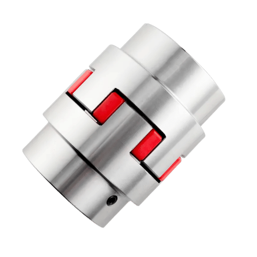
Elastomeric couplings, jaw/spider, tyre, and bushed-pin types, carry torque through a resilient polymer that compresses or shears. Their strength is what rigid and metallic couplings can’t do: they damp torsional vibration and absorb shock spikes, and many are fail-safe in the sense that a worn spider still limps along on metal-to-metal contact. Best for motor-to-pump and motor-to-compressor drives, conveyors, and anything with start-stop or reversing shock.
The trade-offs are equally real, and they’re where field mistakes happen. Elastomers add backlash, the spider is a wear part with a finite life, and the polymer caps the operating temperature. The single most common selection error practitioners report is the wrong spider durometer, too soft and it overheats and tears under torque; too hard and you lose the vibration damping you bought the coupling for. Industry failure analyses converge on the same headline: excessive misalignment is the leading cause of coupling failure, because it drives loads past the elastomer’s capacityrotor-dynamics analysis of coupling misalignment forces traces those loads straight back to the bearings.
When an axis can’t tolerate backlash, a servo positioning a ballscrew, an encoder reading shaft angle, a motion-control stage, the answer is a flexible metallic coupling: beam (helical), bellows, disc, or diaphragm. These transmit torque through a thin metal element that bends to absorb misalignment while staying torsionally stiff, so the driven side follows the driver with effectively zero lost motion. They need no lubrication and shrug off temperature where elastomers melt.
Choose a bellows coupling when you need the highest torsional stiffness and true zero backlash at modest torque and small misalignment — typically around a millimeter of parallel offset and a couple of degrees of angular, depending on size and series, with torsional stiffness on the order of 1,000–50,000 Nm/rad. Step up to a disc coupling when the axis still needs zero backlash but carries higher torque at higher speed. Both suit servo, encoder, and lead-screw drives where a jaw coupling’s backlash would corrupt positioning accuracy.Disc and diaphragm couplings extend the same zero-backlash idea to turbomachinery and high-power drives. Patent activity tracks the demand: recent filings such as a compensating dual-disc coupling (US 9,644,638) mount the element in a zero-backlash fashion on a smooth shaft, confirming that low-lost-motion precision is where coupling engineering is moving. For these parts the tight-tolerance machining of the hub and element matters as much as the catalog rating.
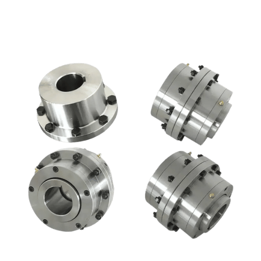
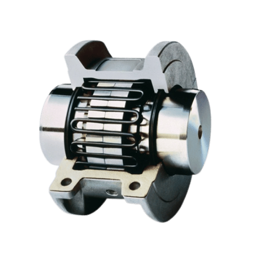
At the high-torque end, gear and grid couplings carry the most torque per unit of size. A gear coupling meshes external hub teeth with an internal flange ring, giving very high torque density and moderate misalignment capacity, the kind of compound offset that technical studies of coupling misalignment in rotating machinery link to higher vibration, at the cost of regular lubrication and maintenance. A grid coupling threads a serpentine spring-steel grid through slotted hubs, adding torsional flex and shock damping while keeping high torque; it also needs grease and a cover.
Best for pumps, compressors, mills, and large motor drives. Where the problem is geometry rather than torque, two specialists take over: the Oldham coupling handles large parallel offset with low backlash (and its center disc is designed to fail first, protecting the rest of the drive), while the universal (Hooke) joint handles large angular intersection, remembering that a single U-joint produces an oscillating output velocity, so pairs are used to cancel it.
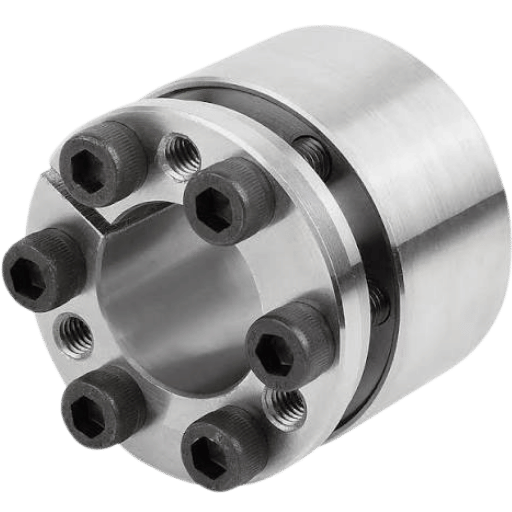
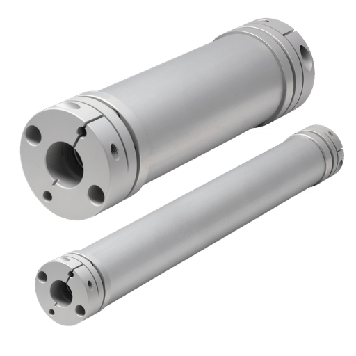
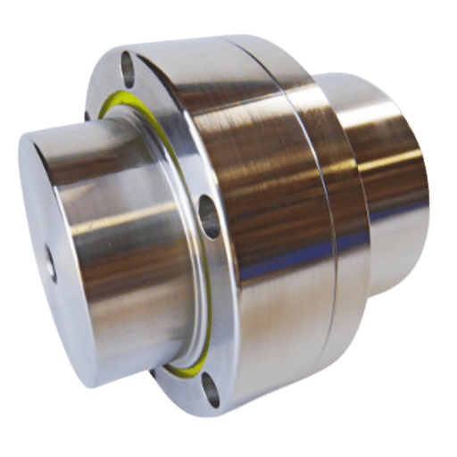
Choosing the coupling type is only half the decision; the other half is how its hub grips the shaft. This is the 4 Hub Connection Lineup, and it changes torque capacity, backlash, and serviceability as much as the coupling body does.
The 4 Hub Connection Lineup
With the families and connections in hand, run your drive through five factors in order. They turn “which coupling looks good” into “which coupling my application requires.”
The 5 Design Factors
📐 Engineering Note — The Misalignment Reaction Load Curve
Here’s the factor catalogs gloss over: a flexible coupling does not erase misalignment. University rotor-dynamics studies show the coupling converts shaft offset into a cyclic reaction force, and the load that appears at the bearings has the same magnitude as that reaction force with the opposite sign, it scales with the offset and is largely a dynamic effect that’s “virtually undetectable in static cases” but real under rotation. In other words, a forgiving coupling protect the coupling, not the bearings. Flexible couplings don’t eliminate alignment requirements; they buy you margin, not a pass. Align to the tighter of your coupling’s spec and your bearing life target, then let the coupling absorb only what’s left.
A flexible coupling buys alignment margin, not a pass. The offset a coupling “absorbs” still returns to the shafts as a cyclic bearing load, which is why field reliability work keeps naming excessive misalignment, not coupling brand, as the leading cause of coupling failure.
Synthesis of published coupling failure analyses and Texas A&M rotor-dynamics findings
A catalog coupling stop at bore size and torque rating. A custom shaft coupling, a non-standard bore, an unusual length, a specific material or balance grade, a profiled hub, is defined by the machining details that never appear on a product page. As a precision CNC machining factory, this is where most of the real selection live.
Bore-to-shaft fit. The hub bore is machined to an ISO 286 fit chosen for the job, not an arbitrary “tight” hole: a location-clearance fit around H7/h6 for keyed or clamp hubs that have to come off, or a light interference around H7/k6 for shrink and integral hubs that stay put. Get this wrong and a removable hub seizes or a permanent hub creeps.
Keyway standard. Keyways follow ASME B17.1 or DIN 6885 parallel-key dimensions; the key width and depth are set by shaft diameter, not by preference, and the corner radius affects fatigue at the keyway root.
Under ISO 21940-11 (formerly ISO 1940-1), the permissible residual unbalance equals a grade-specific eccentricity times the rotor mass, and it shrinks as speed rises. General machinery sits around grade G6.3, high-speed drives around G2.5. The practical window: below a few thousand rpm a well-machined coupling often needs no separate balancing, but as the assembly climbs past its grade threshold the custom coupling must be dynamically balanced as part of the rotor train, in one or two planes.
Material, length, and finish. Steel for strength, stainless for corrosion or washdown, aluminum for low inertia; black-oxide or passivation for the finish; plus the overall length, runout callout, and any lightening that affects inertia. Pull those together and you’ve a complete, quotable drawing.
The Made to Print Coupling Worksheet
Send these seven lines and a machine shop can quote a custom coupling without a back-and-forth:
For a custom coupling we machine the hub, bore, keyway, and any spline in-house on CNC turning and CNC milling, with wire EDM for crisp keyway and spline forms and Swiss machining for small-diameter precision hubs. Our shop holds tolerances to a best of ±0.005 mm and runs under ISO 9001:2015, IATF 16949, AS9100D, and ISO 13485, which is the certification stack that makes a made-to-print coupling repeatable rather than a one-off. The same discipline underlies our shaft machining work.
Have a drawing or a sample? Send the seven worksheet lines for a same-week quote.
Two forces are reshaping coupling demand. The first is precision: servo, robotics, and electric-vehicle drivetrains keep pulling buyers toward zero-backlash bellows and disc couplings, and one market analysis puts the shaft-coupling market near USD 3.6 billion in 2025, with estimates across research firms clustering around a 4.7–6% CAGR through the mid-2030s, directional figures, not a precise forecast.
The second is data: IIoT condition monitoring now watches coupling and alignment health continuously, catching the misalignment that drives most failures before a bearing let go.
Materials are moving too, composite and carbon-fiber spacer couplings can cut rotating mass dramatically and, by lowering the rotating mass, reduce or remove the balancing step at high speed. For most plants the near-term action is simpler: budget for proper alignment and, on any high-rpm or precision drive, specify the coupling’s ISO 21940-11 balance grade up front rather than discovering it during commissioning.
We machine custom shaft couplings, hubs, bores, keyways, and splines, rather than sell a fixed catalog, so this guide is written from the print side of the part. The type behavior here’s cross-checked against industry coupling engineering sources and university rotor-dynamics studies; the fit, keyway, and balance details reflect how a precision CNC shop actually quotes and holds a made-to-print coupling. Reviewed by the Le Creator Technology Co., Ltd. technical team.