Supportive, Professional, Client-Focused Service
Get in touch with Lecreator Company
From prototypes to full-scale production, we’ve got you covered.


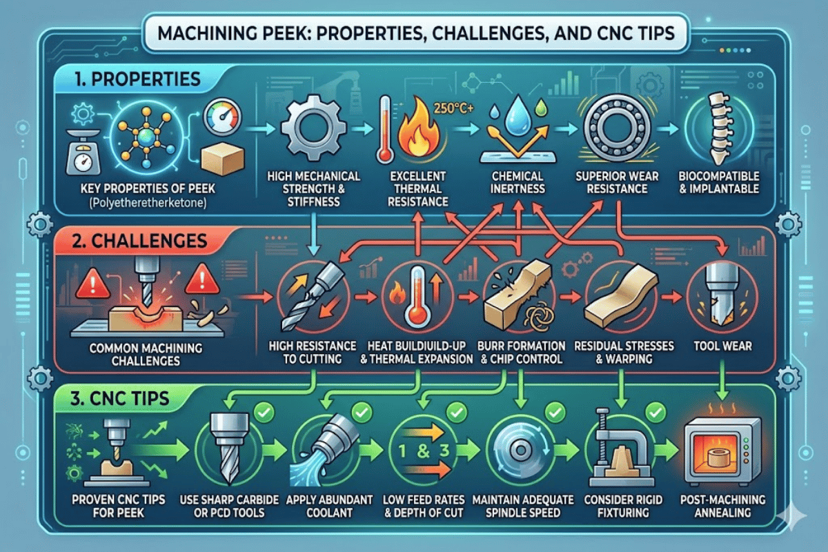
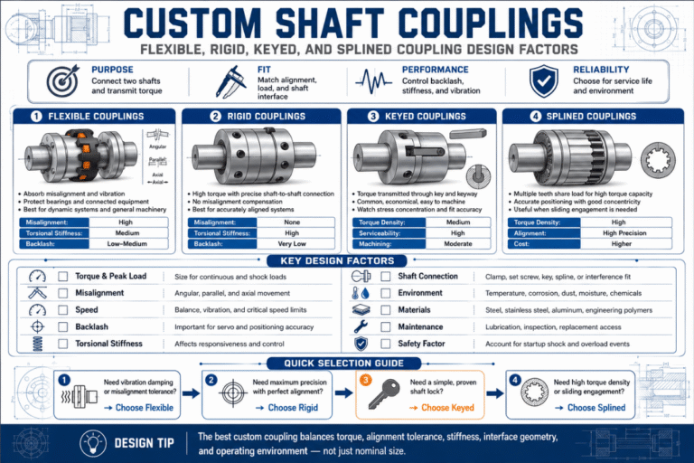
Machining PEEK: What Every Engineer Should Know Before Cutting This Thermoplastic
| Parameter | Value |
| Glass Transition Temp (Tg) | 14³ °C (289 °F) |
| Melting Point | ³43 °C (649 °F) |
| Tensile Strength | 90–100 MPa |
| Young’s Modulus | 3.6 GPa |
| Thermal Conductivity | 0.25 W/m·K |
| Density | 1.32 g/cm³ |
| Continuous Service Temp | Up to 250 °C (482 °F) |
| Water Absorption (24h) | 0.1% |
| Key Standards | ASTM D8033, astm.org/f2026-17.html”>astm.org/f2026-17.html”>ASTM F2026 |
PEEK is one of the most difficult plastics to machine—however the experience of machining it successfully and efficiently is immensely satisfying. With heat resistance, chemical inertness and tensile strength similar to metals, PEEK is the engineering plastic of choice for replacing metal components for use in everything from spinal implants to jet engine seals. Take a quick tour through the tooling, feeds and coolant choices and the annealing techniques that make or break a successful PEEK CNC machining operation.
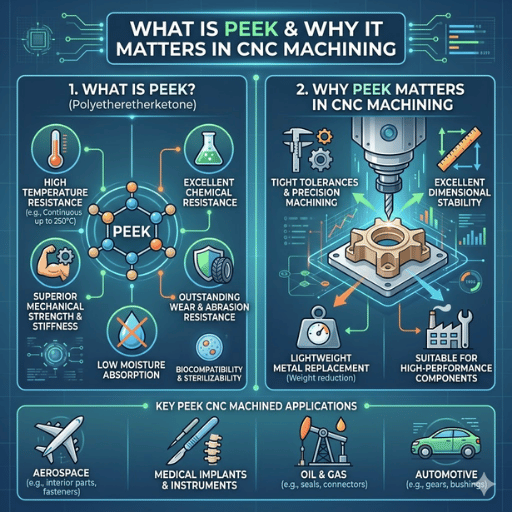
Polyether ether ketone (also written polyetheretherketone) or PEEK is a semi-crystalline polyaryletherketone (PAEK) thermoplastic polymer. It was first synthesized by Victrex in the 1980s and has established itself as one of the most high-performance engineering plastics for CNC machining processes. It is easy to understand why the machinist treat it differently to other thermoplastics such as nylon or acetal with these properties.
The PEEK material is unique in several quantifiable ways. Its continuous operating temperature is 250 °C—around 5x POM. Tensile strength hovers around 90-100 MPa, similar in strength to a high-alloy aluminum. Density only reaches 1.32 g/cm. Combined, these properties make it ideal for light weight load-bearing structural components, such as those in the aerospace industry.
Its chemical inertness extends across hydrocarbons, strong acids and many organic solutions. When used in medical applications, the biocompatible Nature of PEEK(as docμmented in ASTM F2026-17) means it is suitable for direct seating in spinal fusion cages, dental abutments and fixtures, etc. In electronics, its very low outgassing characteristics, stable electrical dielectric thermally in cycling.
The key quality that makes this high performing polymer both desirable and impossible to machine is this same thermal stability. PEEK does not exhibit the typical thermoplastic. Instead, it maintains its strength right up to its transition temperature of 143 °C, then transforms abruptly. It is this narrow temperature window that keeps the heat generated during machining constrained at the tool-workpiece cutting zone, as described in the following.
Key takeaway: With its ability to tolerate high heat, chemicals and moisture easily, in addition to its biocompatibility and mechanical properties, PEEK has few applications to replace—yet those same properties pose some distinct machining challenges.

Machining PEEK is entirely feasible but punishing to any shortcuts taken. Three material properties account for most of the issues machinists face; each one must be countered with these machining techniques to prevent scrap parts or deformation after CMM inspection.
⚠️ Challenge 1: Heat Buildup and Thermal Damage
PEEK has a very low thermal conductivity, only 0.25 W/mK. For comparison, copper conducts at 385 W/mK—around 1540x faster. During machining, heat generated from friction cannot pass through the work material, but instead builds up at the cutting zone, raising the local temperature in excess of PEEK’s glass transition point of 143 C. Gumming results on the tool edge, surface cracks occur from thermal shock when the coolant finally contacts the hot surface. Incorrect feeds hasten this process.
⚠️ Challenge 2: Residual Stress and Warping
Stock PEEK—whether extruded rod, blank, or plates—has residual stress locked in from the extrusion/moulding/grinding operation. Machining into subtracts material, upsetting the natural stress balance—thin-walled features distort flatness levels—parts dimensionally correct machined but ‘de-novo’ hours and even days later as residual stress compensates. The crystalline/amorphous distribution of the work material determines how part deform, reacts to the cut—introducing value-added heat treatment into the process would increase work-flow delay and cost.
⚠️ Challenge 3: Material Cost and Zero Waste Tolerance
PEEK resin is over $100/kg—10-20 times the cost of POM or nylon, for example. A discarded part of a 50 mm dia. rod sample (roughly 6000 mm 2 area) can be a $30–$80 source of raw material loss, as it is advanced through various steps (excluding machining time). Such cost pressures for this level of raw material expense will result in burr and tool wear characteristics that may not be tolerable in the lower cost plastics.
Therefore PEEK shops will tend to run smaller batches, inspect more frequently, and maximize machining efficiencies by nesting parts as much as possible and producing near-net-shape blanks.
Main point: The three issues thermal isolation, internal stress, and price (cost of material) are additive in nature. Solving only one and neglecting the others will still result in rejects. A successful process will tackle all three issues at once.
Tool choice for PEEK is really practically limited to what grade you are cutting. Unfilled glass filled, and carbon fiber filled PEEK all cut with very different processes and not optimizing that tool type will result in factor 10 differential wear. Below is a simple decision guide used by most production shops.
| Tool Type | Best For | Relative Tool Life | Cost Level |
|---|---|---|---|
| C-2 Carbide (fine-grained) | Unfilled / natural PEEK | Good (500+ parts typical) | Low–Medium |
| PCD (Polycrystalline Diamond) | 30% glass-filled PEEK | Excellent (5–10x carbide) | High |
| Diamond-tipped / CVD Diamond | Carbon fiber reinforced PEEK | Excellent | Very High |
| HSS (High-Speed Steel) | Not recommended | Poor (rapid dulling) | Low |
Carbide inserts C-2 for unfilled PEEK will work well, but must be finely ground and sharp, – ie not sintered edges. Asharp carbide rake will cause too much friction and overheat the PEEK, softening above its melting point (> 138 °C). It is best to replace dull tips as they begin to round off, rather than wait until they are visibly worn.
Glass filled PEEK (roughly 30% glass fiber in a PEEK matrix) is abrasive enough to degrade carbide edges in a few dozen parts. While the cost of PCD tooling is higher, longer tool life (5-10x) makes it cheaper per part for production runs above 50. Silicon carbide cutting tools can sometimes be suggested for ceramic composites however these are not compatible with glass filled PEEK.
Requires diamond-tipped tools for milling. Carbon fibers are harder than glass ones in CF-PEEK, and they are oriented in directions that significantly accelerate localized wear of non-diamond edges and tips. CVD diamond coated end mills are now all common as standard milling tools for CF-PEEK parts.
📐 Engineering Note: Rake and Relief Angles
Minimum positive rake of 6-15 with all grades for PEEK is optimum to induce chip formation and to cut and avoid the material being pushed as opposed to being cut away. 10-15 relief angles are recommended to avoid rubbing. These geometry recommendations are similar between turning inserts and milling cutters but significantly different from the zero degree rake angles used for ferrous metals on the same machines.
Pre-embargo key lesson: Choose tool based on what PEEK you’r machining: carbide is fine for unfilled, PCD for glass-filled. Diamond for carbon-fiber variants. It doesn’t matter as much how much the actual tool costs–what will matter more are the economics of the part that run out on a production batch.
The correct machining parameters for PEEK exist at a narrow range. Too slow means too much heat enters the workpiece as the chip dwells. Too fast, and the workpiece gets too hot, and a lack of chip flow packs heat back into the cut. Drake Plastics—a rare hat trick as far as PEEK companies go, as they extrude and machine stock shapes—sets out reliable “ramp-up” data production shops can tweak:
| Operation | Speed | Feed Rate | Depth of Cut |
|---|---|---|---|
| Milling | 500–700 SFM | 0.010–0.040 in/tooth | 0.060 in (1.5 mm) typical |
| Turning | 400–600 SFM | 0.005–0.015 in/rev | 0.040–0.100 in |
| Drilling | 200–400 SFM | 0.003–0.010 in/rev | Peck cycle recommended |
The recommended speeds and feeds for milling PEEK at 500-700 SFM on the surface at 0.010-0.040 in/tooth give nice chip flow that helps carry heat away. MDFN is also a nice cut depth for tending force levels and providing reasonable throughput. Going deeper by too much—more than 0.100 in/ pass—tends to cause deflections on thin sections, while blowing out the thermal limits of heat transfer up those same walls.
Turning speeds (400-600 SFM) and feeds (0.005-0.015 in/rev) reflect material removal with minimal force settling. Wraps are best to clean sections, but perforations or other interrupted cuts lead to more attention of sharpness on inserts. Drilling requires peck cycles to clear chips from the hole before pack heat together. Chunks too big over 3 X-dia will bake the edges and lend to additional tear.
MAINTENANCE NOTE: Coolant choices heat up, cool down—quickly. In the heat of roughing big parts, make many chip trips with air alone. When the chips really don’t clear, wear oil mist instead of flood:
Flood coolant—standard machine default—may actually be a cry for PEEK’s brittle nature. A temperature differential from a warm cutting zone (120–160 °C) to cold room-temperature coolant (~20 °C) leads to a rapid contraction rate over micro-cracks in the surface that damage its integrity.
Compressed air is the right choice for the first response, as it does not add uniform or non-uniform thermal gradients. Oil mist (for blue or blackened aging) should only be used in aggressive roughing passes; otherwise, the thermal gradient has too great an effect on part quality.
For completed biomedical PEEK parts, machine as mat-clean and dry. Any excess or residual coolant—regardless of type—would impede the structure’s ability to pass ASTM F2026 biocompatibility testing.
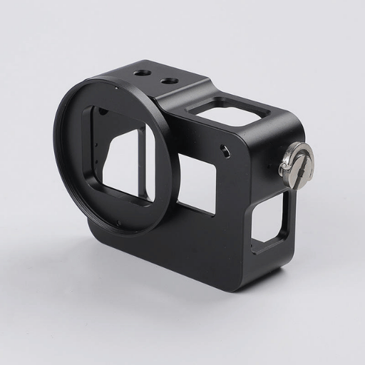
Surface finish on machined PEEK is typically Ra 1.6–3.2 μm with standard parameters and knife-sharp tooling. That level meets most industrial sealing and bearing needs. Since tighter surface finish standards exist—Ra 0.2–0.4 μm—secondary polishing with abrasives of fine grains is needed. Pre-finishing on machine may be performed on the order of 2500-25000 mm/min after care of work table, pathway, and fixturing, whereas dedicated hand finishing with abrasives yields a more consistent part.
Lecreator’s precision PEEK parts manufacturing center includes a dedicated PEEK production cell with a controlled environment and dedicated tooling to maintain the precision this material requires:
In the fundamental lessons, start from published data from Drake Plastics, choose air as a default coolant and specific no flood delay different tool profiles accordingly and expect you’ll need some post-machine polishing in finer surface qualities from a secondary abrasive set.
1.2.3 Processing Characteristics
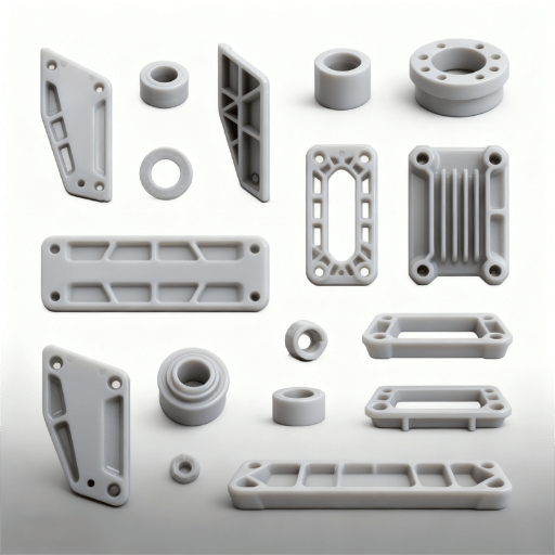
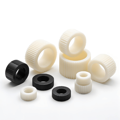
Pursuing that thought further, not all PEEK is created equal. Grade selection determines tooling, parameters, and cost- and the wrong grade for an application can be downright expensive. Four general groups are used to classify most CNC-machined PEEK parts- and each presents different machinability factors to the shop:
| Grade | Tensile Strength | Tg / Service Temp | Tool Requirement | Relative Machinability |
|---|---|---|---|---|
| Unfilled (Natural) | 100 MPa | 143 °C / 250 °C | Carbide | Best |
| 30% Glass Filled | 157 MPa | 143 °C / 250 °C | PCD | Moderate |
| Carbon Fiber Reinforced | 212 MPa | 143 °C / 250 °C | Diamond | Difficult |
| Medical Grade (Implant) | 100 MPa | 143 °C / 250 °C | Carbide (dry only) | Best (process-sensitive) |
Unfilled (natural) PEEK machines the least amount of dirt. The Victrex PEEK 450G data sheet specifies a tensile strength of 100 MPa with a 30-40% elongation at break. Such ductility results in the formation of smooth chips which tend to evacuate without fracturing.
Natural PEEK is the standard by which seals and bearings are made along with electrical insulators where dirt resistance (abrasion resistance) is of little importance. This is the starting point for the vast majority of PEEK plastic components unless a derivate is specifically needed.
Glass filled PEEK (usually 30% by weight) increases the rigidity modulus form 3.6 GPa to about 11 GPa and enhances creep resistance at elevated stress level for long durations. Disadvantage of the glass fiber reinforced stock is abrasive effect. Carbide tools which last over 500 parts for unfilled PEEK may last only 50-80 parts on the glass filled stocks before the edge dullness compromise surface finish quality.
PCD tooling will be the cost effective decision for batch sizes above 30-50 pieces.
PEEK CG50 CF has tensile modulus over 200 MPa and density below 1.45 g/cc. It is often used in aerospace structural applications and high performance racing products where weight saving outweighs other considerations. Carbon fibers are much harder than glass fibers and tend to produce fine abrasive dust during machining.
If diamond tooling is not used then it had better be optional! Tool wear data collection while machining CF-PEEK should be more controls than for other PEEK grades.
Medical grade PEEKperASTM F2026-17 is chemically identical to Natural PEEK, but manufactured with certified feedstock traceability and biocompatibility testing. Machine parameters and tooling is the same used for Natural PEEK. Where it differs is in the processing environment dry machining only, no coolant contamination, with fixturing dedicated to the Medical grade material and not cross-contamination with Natural PEEK.
The potential Medical grade PEEKapplications are: spinal fusion cages, cranial implant plates and dental abutments. All of these fall under the cytotoxicity and implant-site testing.
The industrial grade PEEK astm.org/d8033-22.html”>ASTM D8033-22 meets standard mechanical and electrical specifications and does not include certification for biocompatibility. This industrial grade PEEK has found common use in ASTM injection molded PEEK pieces for high-volume manufacturing but CNC has remained the standard for prototype and low-volume manufacturing.
⚠️ Common Mistake
Indication of unfilled PEEK where 30% glass filled is specified. Historical field failure data indicates unfilled PEEK in high wear bearing type applications can experience creep and dimensional change or set when subjected to sustained loading above 20 MPa. In applications that continually load mechanically, glass filled or CF-PEEK should be the default, not the upgrade.
What to remember: Choosing grades is an engineering decision, not a purchasing decision. First choose the correct filler grade for your load case. Then determine the tooling and control parameters to suit that grade.
Tolerancing ability of machined PEEK components falls into three categories-the part feature geometry, the part’s heat treatment state-annealed or unannealed, and the degree of stock removal with respect to the equipment. Whereas for metal components machinability closely translates to tolerances, PEEK does not work the same.
| Tolerance Level | Range | Typical Application | Cost Impact |
|---|---|---|---|
| Standard | ±0.05 mm | Structural brackets, covers | Baseline |
| Precision | ±0.025 mm | Seals, bearing surfaces | 2–3x baseline |
| High Precision | ±0.012 mm | Medical implants, semiconductor | 4–5x baseline |
Reducing from 0.05 mm to 0.025 mm triples or doubles part price for similar reasons as above; more annealing between rough and final; tighter process controls; inspection by CMM post-machining on every part. At 0.012 mm it jumps even further: 4-5X due to controlled-environment machining, CMM verification, multi-annealing cycles.
This correlation between tight tolerances and annealing is straightforward: no stress relief the PEEK part machined to 0.025 mm could relax by 0.02-0.05 mm in days or weeks after the part leaves the machine, as the stresses build back in. This could result in the part falling out of tolerance even after it leaves the machine.
The annealing process as suggested by Boedeker Plastics involves a two step process which aims at relieving the machining stress as well as improving the crystallinity of the part for dimensional stability:
📐 Engineering Note: Two-Stage PEEK Annealing
Stage 1 – Stress Relief: Ramp oven to 300 °F (149 °C) at 50 °F/hr. Hold for 60 minutes per 0.25 in. of maximum cross section thickness. This temperature is slightly above the glass transition temperature and enables the molecular chains to relax without changing crystalline phase.
Stage 2 – Increased crystallinity: 300 °F to 375 °F (191 °C) at 50 °F/hr. Include a second soak for 60 minutes for every 0.25 inches thick of the bag. This time will further increase the degree of crystallinity, and will provide chemical resistance and long term dimensional stability.
Cooling: Decrease temperature at a rate of 50 °F/hr no more until below 200 °F (93 °C). Do not open oven door during cooling, the thermal shock resulting from the ambient air when door is opened can reapply the stresses you’ve just finished removing. Maintain support of the parts on flat fixtures through out the entire cycle to prevent sag or distortion of the part’s geometry.
For PEEK parts and PEEK features with tight tolerances, many shops use a rough-anneal-finish cycles: rough machine to 0.5mm of final dimension, anneal, and machine to final tolerance. This keeps the finishing cut from being relaxed away by stress relaxation after machining. Extra cycle time is costly, but provides significantly higher yields for tight tolerance features.
Surface cracks can form if the heating is omitted for heavily machined specimens. These micro-cracks, while unnoticeable without dye penetrant inspection. Micro-cracks of this type can also be discovered through pressure testing.
For fluid seal and vacuum conditions, annealing is not an option but a specification.
The important point is that, for PEEK, annealing is not optional. For any dimension that needs to be held in 0.025mm or less, or for any part with walls that are thin in comparison with stock size, the rough-anneal-finish cycle is the sure way to achieve dimensional stability and no surface cracks.
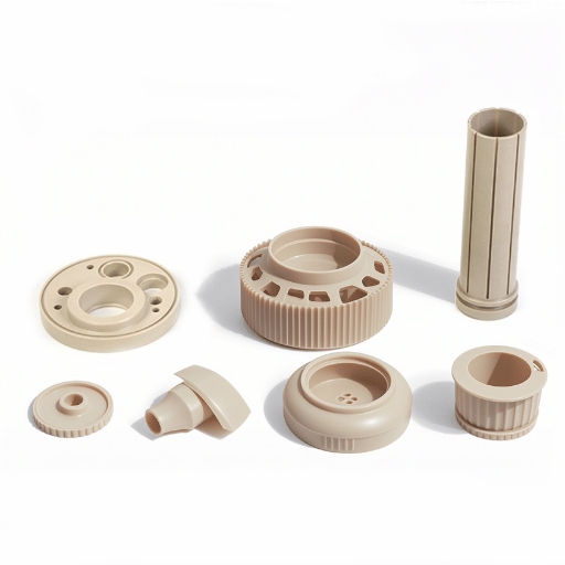
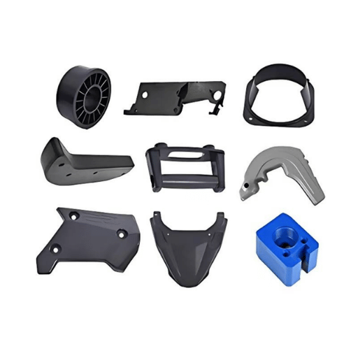
Applications span multiple industries where no other polymer offers the combination of temperature, chemical and load resistance. Different application areas take advantage of different subsets of PEEK properties and consequently have different machining requirements.
✔ Aerospace
Engine manufacturers, who operate structural brackets, seals and bearing cages at sustained temperatures above 200 C in engine nacelles and bleed-air systems, are increasingly substituting machined PEEK rather than aluminum and titanium brackets, which results in savings of 40-70 percent weight. The lead time of producing aerospace-components out of machined PEEK stock has been practically and steadily decreasing. OEMs are looking at a lighter and more corrosion resistant substitute of metal in the form of this high performance polymer for a wide array of components.
✔ Medical Devices
Medical implants such as spinal fusion cages, cranial plates or dental abutments rely on the biocompatibility of medical grade PEEK components. These parts are radiolucent (i.e., transparent to X-ray unlike metals like titanium). Each implant grade product requires dry machining, lot-controlled stock or granulate and ASTM F2026 compliance. Adoption of PEEK as an orthopedic implant material is increasing at an accelerating pace.
✔ Automotive
Transmission thrust washers, under-hood sensor-housings and turbo charger parts require PEEK parts to withstand continuous elevated temperatures over 200 °C, and exposure to oil and fuel. In electric vehicles, PEEK insulators are replacing ceramics in high-voltage battery module connectors because they are easier to mold and machine into exact geometry while saving weight.
✔ Electronics and Semiconductor
Wafer-handling arms, test socket insulators or vacuum chamber components must exhibit low outgassing, high purity and dimensional stability over several thermal cycling. PEEK as a material delivers on all three criteria and can be machined to the 0.012 mm tolerances that semiconductor equipment demands. Usually, prototypes are machined on CNC machines before moving to PEEK injection-molding or CNC-molded production parts.
However small or large the PEEK service component production run, skill and experience are required of the CNC machine shop that machines the parts. At Lecreator, 98% of our plastic machining jobs pass the first time and our customers enjoy total traceability of the imported raw material.
Summary: No other polymer is seeing such an increasing use across various industries as PEEK because each application demands a unique set of performance attributes which no other machinable polymer currently offers. From aerospace to medical to semiconductor applications, each niche has its own machining idiosyncrasies but the end result is consistently a high performance assembly.
Lecreator machines PEEK parts to 0.025 mm with 98% first pass yield. Send your drawings for a free quote.
This article and the data it refers to was written by Lecreator (Shenzhen Le-creator Technology Co., Ltd.). We run 80+ machines over 17 years of production experience to CNC machine PEEK and other metals and plastics for aerospace, medical and industrial applications day-in-day-out to a tolerance of 0.025 mm with a first pass yield of 98%. The information referenced here is taken from published data sheets for the individual material being used and industry standards. It is no way a Lecreator marketing exercise and we earnestly provide it to hopefully help you better understand PEEK.