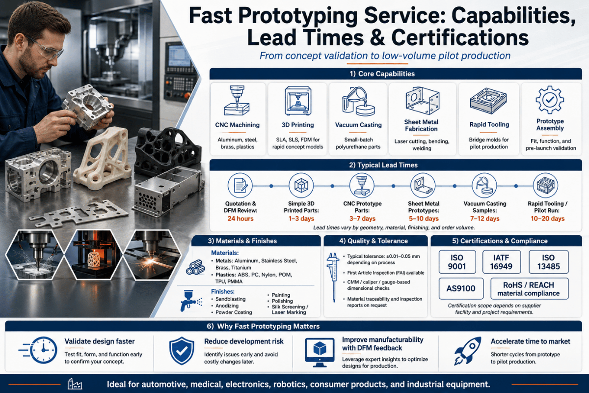
Supportive, Professional, Client-Focused Service
Get in touch with Lecreator Company
From prototypes to full-scale production, we’ve got you covered.


Whenever your product team just needs a quick prototyping service, the process decision precedes the supplier decision – and simply choosing the wrong one can cost you weeks and thousands of dollars in rework. This guide will compare every major rapid prototyping method along verified tolerance specs, real cost ranges, and lead-times – then provide you the decision frameworks to identify the correct process, correct material, and correct vendor for your team’s particular stage.
Map your project’s requirements against your options before approaching any suppliers. The chart below cross-references surface finish, dimensional accuracy, minimum wall thickness, and lead-time for all mainstream rapid prototyping technology. Tolerance ranges are representative of the ISO/ASTM 52902 dimensional accuracy benchmark framework and the specs of their secured supplier network.
| Process | Tolerance | Lead Time | Min Wall | Surface Ra | Best For |
|---|---|---|---|---|---|
| SLA | ±0.05–0.1 mm | 1–5 days | 0.6 mm | 0.1–0.4 µm | Visual, dental, medical models |
| SLS | ±0.1–0.³ mm | 3–7 days | 0.7 mm | 10–15 µm | Functional nylon/PA parts |
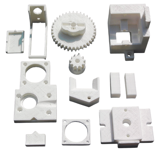
| FDM | ±0.3–0.5 mm | 1–3 days | 1.0 mm | 12–25 µm | Concept models, cost iteration |
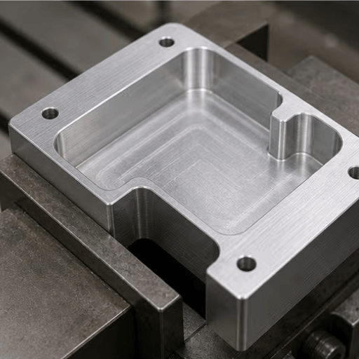
| CNC Machining | ±0.01–0.025 mm | 3–7 days | 0.8–1.5 mm | 0.8–3.2 µm | Metal parts, tight tolerance |
Dimensioning scope per ISO/ASTM 52902 benchmark framework. Master values depend on geometry, material, and machine configuration.
No one process is better than the others for all requirements. SLA offers the best surface finish; CNC offers the tightest tolerances; FDM offers the fastest build time at the lowest cost. The below chart is a pre-filter – your material requirement will determine your final selection.
A rapid prototyping service manufactures a physical model from a 3D CAD file in 1-5 days using additive manufacturing, CNC machining or both. The core value-added is speed, enabling the team to have the physical models in hand by half the typical lead time (1-5 days vs 4-12 weeks) so they can start validating fit, function, and aesthetics before locking into production tooling that can cost $10,000–$100,000+. Across the full product development cycle, this time compression is the primary value a fast prototyping service provides. In these scenarios, the prototype is an iterative work-in-progress instead of the final manifestation.
For example, a medical device startup during Phase 2 of design validation. Their in-house FDM printer capable of overnight concept models can’t produce fastenings or enclosures with 0.05 mm tolerances for cable routing or gasket sealing – tolerances their desktop FDM units can usually be trusted to produce consistently. Outsourcing the enclosure to a fast prototyping SLA vendor, at $180 / 3 days, gives the design team accurate physical parts in short order. Building in-house at inadequate tolerance would mean re-ordering after assembly failure, which delays the launch by 2-3 additional revision cycles and 2-4 weeks of time.
| Factor | Build In-House | Outsource Prototype Service |
|---|---|---|
| Tolerance achievable | ±0.3–0.5 mm (desktop FDM) | ±0.05 mm (SLA) / ±0.01 mm (CNC) |
| Material range | 2–5 FDM filaments (desktop 3D printers) | 50+ engineering materials |
| Typical lead time | 1–2 days (machine time only) | 1–7 days (door-to-door) |
| DFM feedback | None | Automated + engineering review |
Outsourcing becomes viable when the outsource unit cost of failure is greater than the outsource time or cost, when enabled tolerances, materials or post-processing capabilities are unavailable in-house. For most companies, that breakeven arrives at the functional prototype stage, well before the design is frozen for production runs.
Choosing among rapid prototyping manufacturing technologies involves more than comparing lead times — each process has a distinct geometry envelope, material scope, and post-processing profile. This decision matrix summarizes the most relevant selection factors.
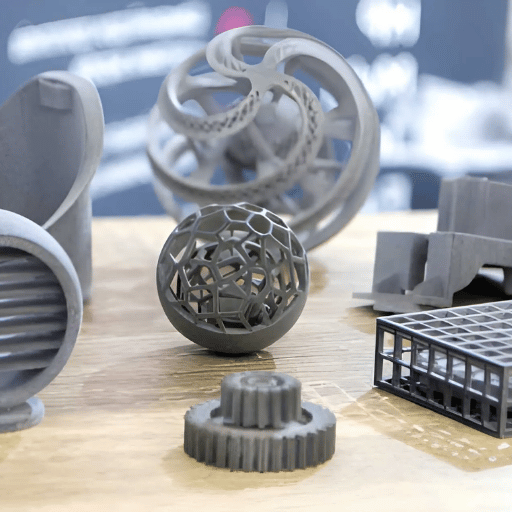
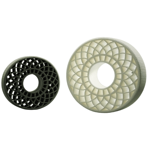
SLA (stereolithography) uses a UV laser to cure liquid photopolymer resin layer by layer, achieving a 0.025 mm laser spot and surface roughness as low as Ra 0.1–0.4 µm — the smoothest finish of all 3D printing technologies. It targets tight tolerances on flat and curved surfaces but requires support structures that leave witness marks. SLS (selective laser sintering) fuses nylon or PA powder without supports, enabling undercuts and complex internal geometries that SLA cannot produce. SLS tolerances run wider (±0.1–0.3 mm), but the resulting 3D printed parts have isotropic mechanical properties throughout. The key decision factor: SLA for surface aesthetics and medical/dental applications; SLS for structural mechanical testing, snap-fit assemblies, and functional prototypes with complex geometry.
✔ When CNC Machining Wins
⚠ When 3D Printing Wins
“Another common, pervasive false belief in prototype sourcing is that CNC machining is somehow slower than 3D printing; In the case of a basic aluminum bracket with bore tolerances of 0.020mm, a 3-axis CNC with a decent level of equipment turns around prototypes on the order of days (just like some industrial SLA systems), with a better level of material performance, repeatability, and dimensional accuracy than is presently feasible for any aluminum additive process.”
| Scenario | Recommended Process | Reason |
|---|---|---|
| Aerospace / defense component | CNC machining + AS9100D | Tolerance + cert requirement |
| Functional nylon mechanism | SLS | Isotropic strength, no supports |
| Consumer product visual model | SLA | High-quality surface finish, best of SL resins |
| Early concept / fit check | FDM | Lowest cost, 1–3 days |
| Sheet metal enclosure prototype | Sheet metal fabrication | Production-representative thickness |
In for those 3D Printing Service projects Process selection also determined by any needed finish, For those SLA parts sanding & painting to quality of production; Those FDM parts, a good quality to coating it, functional; Those FDM thermoplastic parts vapor to polish some like ABS. For SLS nylon Dyeing& any functional coating it is okay.

This is the biggest point where prototype orders go south – it’s not with your supplier, it’s within your own company’s system. We tend to look at which process is first (‘Let’s 3D print it’) then we ask the supplier for whatever materials is appropriate. You have this wrong way around.
The Material-First Rule: Define the material your functional prototype must be made of first — based on the end-use production material or its closest substitute — then select the only process that can produce that material. Engineers who choose the process first accept whatever material it offers, creating property mismatches that account for the majority of re-prototyping cycles. Reverse the order: material → process → supplier.
— Original decision principle, Lecreator Engineering
Here’s a look at the process-first selection in the real world a hardware startup required 10 brackets for an outdoor sensor mount. SLA was used for its finish quality and cost ($120 for the run, delivered in two days). After 8 weeks of outdoor testing, three of the brackets were crazed, showing a 40% decrease in tensile strength.
Since SLA materials don’t hold up to the UV/thermal cycling and the only solution is the material, which requires a different process – glass-filled nylon for structural integrity at extreme temperatures and humidity, a job best done with SLS ($280 for the run but solid, stable material properties to 120C) – the reorder cost $1,800 the hardware startup 6 weeks of their time plus $1,800 a redesigned bracket.
📐 Engineering Note — Material Properties at a Glance
| Material | Process | HDT (°C) | Tensile (MPa) | UV Resistance |
|---|---|---|---|---|
| ABS | FDM / CNC | 75–100 | 40–50 | Poor (stabilizer needed) |
| Nylon / PA12 | SLS / CNC | 160–180 | 50–70 | Good |
| Aluminum 6061 | CNC | 160 (annealed) | 310 | Excellent (anodized) |
| Titanium Grade 5 | CNC | 315 | 950 | Excellent |
| PEEK | CNC | 250 | 100 | Excellent |
| SLA Photopolymer (standard) | SLA | 45–65 | 30–55 | Poor (degrades in UV) |
HDT=Heat Deflection Temperature at 0.45MPa. Data sourced from standard ASTM materialdatasheets. The values above represent standard general data; the actual values will vary by material grade, material supplier, and production parameters.
Material-First Rule. Apply it before opening a quoting platform: name the production material. You are unable to name it yet? Don’t order a functional protoype, you are only ready for conceptual models, which you get cheaply from FDM. (For more detail: how to machine PEEK plastic for prototype and production parts).
The DFM Review. A design for manufacturability(DFM) review is the highest-impact step a buyer can take, andit should take place before ordering is completed. Automated DFM tools are now standardat major on-demand manufacturers (like Hubs and Protolabs), and they spot geometryissues that were once detected by eye (or a telephone call and a 2 dayhold). Automated tools however fail tocatch everything. Below is a checklist of common design errortraps based on widely accepted best practices for bothmachined and added/print manufacturing.
📐 Engineering Note — Minimum Wall Thickness by Process
* SLA: 0.6mm (thinner sections are susceptible to deformation under the stresses associated with removing supports). SLS: 0.7mm (powder does not effectively fuse below this threshold). FDM: 1.0mm (1 extrusion perimeter pass = approx. 0.4mm; a typical structural wall should be 2-3 perimeters thick). CNCmachining: 0.8mm (plastics) up to 1.5mm (metals, varies by tooling, depth-to-width ratio; extremely thin walls can vibrate during cutting). Forany CNC machined part, an unsupported wall thickness to height ratio should remain at or below 4:1.
The most frustrating and costly part about multi-part assemblies is typically finding out at final assembly that there’s a tolerance stack-up problem with three (or more!) parts needing to be remachined. If your prototype is an assembly, be sure to consider the worst-case tolerance chain before ordering it. A 0.2 mm stack-up mistake caught in CAD is free. Caught at the assembly station, it can cost you several days and several hundred dollars.
While price is typically right there on the quote, what is more important to judge (and much harder) – and what determines project risk more than anything – is everything you *don’t* see in the quote, such as the certifications held, the quality of the DFM feedback, the material availability, and delivery promises met. This 7-part framework can help you begin to short-list your potential suppliers for your prototype project:
| # | Criterion | Benchmark Threshold | Why It Matters |
|---|---|---|---|
| 1 | Quality certification | ISO 9001:2015 minimum | Ensures documented process control and dimensional consistency |
| 2 | Quoted lead time | ≤5 days for standard parts | Directly impacts your project milestone risk |
| 3 | DFM feedback | Included with every quote (automated or reviewed) | Prevents design errors from reaching production |
| 4 | Material range | ≥10 engineering materials across at least 2 processes | Single supplier for plastic + metal prototypes reduces coordination overhead |
| 5 | Online instant quotes | Quote in ≤5 minutes after file upload | 3–5 day manual RFQ cycles cost more in engineering time than the part |
| 6 | MOQ | 1-piece minimum | Prototype stage requires single-unit validation before quantity commitment |
| 7 | Post-processing options | ≥3 finishing options (anodizing, painting, bead blasting) | Surface finish validation requires the same post-processing as the production part |
Scenario Decision Matrix
Lecreator’s rapid prototyping service holds ISO 9001 certification, provides standard turnaround times as fast as 1 day for simple parts, and has zero MOQ-addressing most points (1, 2 and 6) in the above framework, and all points with respect to their offering. It works for plastic and metal parts under their framework.
The cost of a prototype depends on the process used, materials chosen, complexity of the geometry, and quantity. Below is a range of costs for a typical prototype (medium complexity, roughly 100 cc volume with no extreme thin walls or undercuts). Figures represent Q1 2025 market rates and are intended for budget planning only — actual quotes will vary.
| Process | Single Unit Est. | Per 10 Units Est. | Primary Cost Driver |
|---|---|---|---|
| FDM | $20–$150 | $10–$80/ea | Machine time + filament |
| SLA | $50–$400 | $30–$200/ea | Resin material + post-processing |
| SLS | $80–$600 | $50–$300/ea | Powder + build volume share |
| CNC Machining | $200–$2,000+ | $100–$800/ea | Machining time + stock material |
Estimated pricing as of Q1 2026. Pricing depends heavily on geometry, materials, quantities, and specific online suppliers. For accurate pricing, request a quote.
FDM (Fused Deposition Modeling) is the most cost-effective prototyping method if cost is your only criterion. A simple to medium-complexity part can be produced for $20-$150. The main drawback to FDM is its low surface quality and dimensional accuracy, the lowest of the four processes. Stick with FDM for concepts where accuracy doesn’t matter and don’t plan on using it for functional prototypes or for aesthetic finishing. If cost is key and the tolerance matters, consider a low-volume CNC machined part in aluminum from an online provider; prices may fall below SLA and provide much better tolerance and strength. Simple rules of thumb: If the part tolerance is tighter than 0.1mm (4thou) the total cost advantage from using FDM almost always evaporates due to re-runs and redesigns; If the part must be water-tight, avoid FDM unless it’s for form and fit validation only.
We observed an electronics startup in a local accelerator getting a quote from an online manufacturer to CNC machine a complex aluminum enclosure with a flatness tolerance on all surfaces of 0.005mm – an unthinking result of the default CAD print accuracy. They were quoted $14,000 USD total from the supplier. It was later discovered through engineering review that only three out of 47 critical surfaces actually required such a tolerance; the other 44 could accept a flatness of 0.1mm. After revising the print and submitting a new quote from the same supplier, the cost was reduced to $420 USD.
Rapid prototyping markets are expanding even as supplier consolidation accelerates. Knowing what the future has in store helps customers select manufacturers who will still be around when a future project comes to be produced.
The global 3D printing/additive manufacturing sector is expected to continue its rapid expansion throughout 2025 and beyond according to global research. Based on new figures, by 2025 global additive manufacturing grew at 9.1% year on year to 21.9 billion (Wohlers Report 2025), with AM now a firmly established technology for prototype and full production-ready components. By 2025, North American demand for rapid prototyping materials increased to USD 318.72 million from USD 311.34 million in 2025, with predicted growth to USD 373.33 million by 2026, an increase of 17% yoy (Fortune Business Insights).
By 2026 Wohlers Associates indicated total AM revenue of 24.2 billion.
Trend 1 – AI DFM now a must, not a must have – Since 2025 many of the leading on-line quoting services now provide live DFM on file upload – wall thickness issues are alerted, tool access problems highlighted, material compliance checks performed with 0 human engineering input. Services that still rely on manual DFM take 3-5 days longer to quote. For the buyer the consequence is obvious – live quoting DFM tooling is now the minimum expectation.
Trend 2 – Hybrid manufacturing (additive and subtractive on one machine workflow) – Many on-demand manufacturing providers route complex part designs through additive and subtractive in a workflow. They add the complexity and base material with additive manufacturing and then clean up the form and finish critical feature with CNC machinery. This solves the trade-off challenge of selecting either speed (additive) or accuracy (subtractive) and can reduce the supplier and lead-time pain for a prototype buyer by offering it on a single, integrated platform.
3- Metal AM has made its way down to what only CNCs are now cost-justifiable at The cost of DMLS/SLM machines decreased 20-35% from last year as the machine time at service bureaus filled up. As such, complex geometries in aluminum and titanium for 1-5 units of low value/complexity may now cost much less using metal AM than via CNC machining.
Implication to buyers undertaking projects in 2026: If evaluating a rapid prototyping provider look for an auto DFM with a quote and ensure they have a hybrid manufacturing model. Vendors taking 3 to 5 day to go through the manual RFQ for a quote are working with a 2020 model in a competitive 2025 and 2026 marketplace. The 3-5 day lead time advantage between an automated and manual quote is the product launch lead time lead.
Truly rapid prototyping service providers are not fast just with the actual parts – but also with their quote, DFM feedback, and order management process. A quoted time longer than 24 hours for a prototype order typically means the delay is in the suppliers process, not their manufacturing time.
Upload CAD to find pricing and DFM feedback for SLA, SLS, FDM, and CNC – 0 MOQ – Available with 1-day turn for standard geometries.
This guide was compiled by the Lecreator engineering team, which provides CNC, SLA, and SLS rapid prototyping to product developers in aerospace, medical, and consumer electronics. Comparative process data, potential costs and tolerances were checked against multiple suppliers’ specs and the ISO/ASTM 52902 guideline for accuracy. Costs are a reflection of 2025 market conditions and should only be used for budget estimation purposes only-quotes will vary based on geometry, materials, post-processing etc.