Ondersteunende, professionele, klantgerichte service
Neem contact op met Lecreator Company
Van prototypes tot productie op volledige schaal, wij hebben u gedekt.


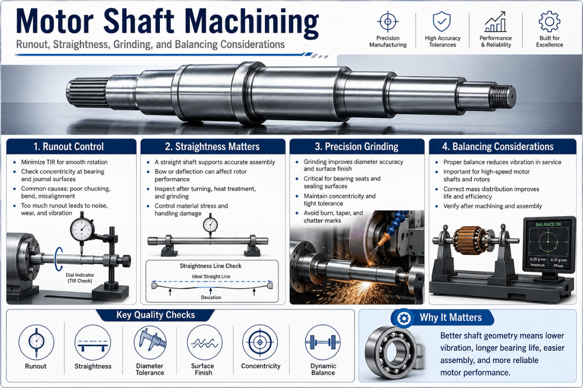
De machinaal bewerken van de motoras is de reeks draaien, frezen, warmtebehandeling en precisieslijpen die staafmateriaal verandert in een voltooide roterende as die wordt vastgehouden aan lagertoleranties, lage uitloop, gecontroleerde rechtheid en een balansgraad die geschikt is voor de servicesnelheid. Zorg ervoor dat een van die vier ongelijk heeft en het symptoom is hetzelfde op de testbank, trillingen, hitte en vroege lagerstoringen, zelfs als de diameter perfect meet. Deze gids behandelt deze vier pijlers als een technisch systeem en niet als een specificatieblad.
Het korte antwoord
Een motoras wordt afgewerkt in een vaste volgorde, ruwe draai, warmtebehandeling, dan slijpen de lagertappen, omdat elke stap vergrendelen in een andere kwaliteitslaag Draaien stelt de vorm (IT7-IT9, Ra ~1.6 µm); cilindrische slijpsets eindgrootte, rondheid, en afwerking op de lagerzittingen (IT5-IT6, Ra 0.2-0.4 µm); GD & T runout verbindt die stoelen aan een gemeenschappelijke as; en dynamische balancering regelt hoe het afgewerkte, roterende deel zich gedraagt op snelheid.
Belangrijkste afhaalrestaurants
| Gedraaide diameter | IT7-IT9, Ra ~1,6 µm |
| Grondlager journal | IT5-IT6, Ra 0,2-0,4 µm (tot ±0,005 mm) |
| Uitloop van tijdschriften (tussen centra) | vaak ≤0,01 mm TIR |
| Gemeenschappelijke materialen | 1045, 4140, 4340, 416/431 roestvrij, Inconel |
| Journal hardheid (inductie) | ~50-60 HRC-oppervlak, taaie kern |
| Balansgraad | G6.3 (algemene motoren, pompen, ventilatoren) tot G2.5 (precisie/hoge snelheid), ISO 21940-11 |

De schachtproductie verloopt in een bewuste volgorde: ruw CNC draaien tussen de middelpunten om de cilinder en de middengatgegevens vast te stellen, optioneel frezen van spiebanen en platte vlakken, warmtebehandeling en vervolgens het slijpen van de lagerzittingen afmaken. Deze volgorde van het productieproces is niet cosmetisch, elke bewerking vergrendelt een kwaliteitslaag waarvan de volgende afhankelijk is, en daarom wordt een as gehard before de tijdschriften zijn grond in plaats van erna.
Waar in deze gids “machining staat, leest” het als de bredere schachtproductiestroom van staafmateriaal naar geïnspecteerd onderdeel.
Het helpt om die lagen als een stapel te beschouwen We noemen het de Shaft Precision Stack: Grootte → Vorm → Uitloop → Saldo. Elk niveau doet er pas toe als het niveau eronder onder controle is, een tap van perfecte grootte nutteloos is als de vorm ervan gelobd is, en een ronde tap nog steeds trilt als de hele as uit balans is.
De Shaft Precision Stack
Draaien en frezen doen het grootste deel van de vormgeving Voor een as uit één stuk die zowel cilindrische als prismatische kenmerken nodig heeft, snijdt een bewerkingsopstelling met walsdraai (multitasking) de tappen en de spiebaan in één bevestiging, die de concentriciteit beschermt door een herklem te vermijden. Als u het twee basisproces weegt, wordt onze afbraak van CNC frezen vs CNC draaien dekt wanneer elke leiding. Boren, tappen en EDM (voor spiebanen in reeds geharde schachten) vullen de rest in. Referenties voor beroepsbewerking, zoals die van het Amerikaanse ministerie van Onderwijs trainingsmateriaal voor werktuigmachines leer nog steeds eerst het draaien tussen centra, juist omdat het elke latere bewerking een stabiele, herhaalbare as geeft.
Belangrijkste afhaalmaaltijden: bepaal de volgorde van de werking rond de Precision Stack, grootte vóór vorm, vorm vóór uitloop, uitloop vóór balans en de meeste stroomafwaartse verrassingen verdwijnen.
Cilindrisch slijpen is hoe een schacht zijn uiteindelijke tapgrootte, rondheid en oppervlakteafwerking bereikt na het draaien. Waar het draaien rond IT7-IT9 en Ra ~0,8-6,3 µm terechtkomt, houdt precisieslijpen ongeveer IT5-IT6 vast bij Ra 0,1-1,6 µm, waarbij de lagertijdschriften gewoonlijk zijn afgewerkt tot Ra 0,2-0,4 µm. In de praktijk wordt het tijdschrift zo gebruikt dat er ongeveer 0,10-0,30 mm slijpmateriaal overblijft en vervolgens op maat wordt gemaakt. Dat verschil is de reden waarom lagerstoelen bijna altijd worden geslepen, en niet alleen worden gedraaid, een onderzoek naar cilindrische en oppervlakteslijpparameters die zijn gepubliceerd door de Amerikaanse National Institutes of Health's PubMed Central laat zien hoe de wielsnelheid, voeding en snedediepte direct de haalbare afwerking aandrijven.
Kies de maalmethode op basis van geometrie, vastgelegd in de Ladder met tolerantie voor procesvermogen below.
| Process | Typische tolerantie | Oppervlakteafwerking (Ra) | Best for |
|---|---|---|---|
| CNC draaien | IT7-IT9 | ~0,8-6,3 µm | Ruwende, niet-kritische OD, schouders |
| OD cilindrisch slijpen | IT5-IT6 | 0,2-0,4 µm | Lagervlakken, afdichtingsoppervlakken |
| Centerless slijpen | IT5-IT6 | 0,2-0,4 µm | Lange, slanke schachten met een hoog volume |
| ID slijpen/honen | IT5-IT6 | ≤0,2 µm | Holle-asboringen, taps toelopend |
Procesbanden samengesteld op basis van slijpgegevens uit de industrie (Modern Machine Shop, schuurmiddelenfabrikanten) en het PubMed Central-slijponderzoek; De werkelijke resultaten variëren afhankelijk van de stijfheid van de machine, het wiel en het koelmiddel.
Voor interne boringen op holle assen, honen brengt de afwerking een stap verder dan ID-slijpen Een nuttig voorbehoud van de metrologische kant: slijpen is dat niet categorisch de enige route naar een fijne finish Het Amerikaanse National Institute of Standards and Technology heeft die precisie gedocumenteerd hard draaien van gehard gereedschapsstaal kan oppervlakte eindigt beter dan 80 nm Ra bereiken, rivaliserende slijpen in sommige afwerkingsgevallen Slijpen wint nog steeds waar u strakke grootte, rondheid, en samen eindigen op een geharde journal, maar de keuze is toepassingsspecifiek, niet automatisch.
📐 Engineering Note oppervlakte-integriteit, niet alleen Ra
Een journal kan een perfecte Ra meten en toch vroeg falen Agressief slijpen kan een thermisch beschadigde “ laag, resttrekspanning en een broze witte laag net onder het oppervlak achterlaten, die vermoeiingsleven vergaat Academisch werk over slijpverbranding (bijvoorbeeld het proefschrift gearchiveerd op de Universiteit van Nebraska, Lincoln) laat zien waarom bij het afslijpen gebruik wordt gemaakt van lichte passages en voldoende koelvloeistof. Geef aan hoe de tap is afgewerkt, niet alleen het nummer dat hij moet raken.
Belangrijkste afhaalmaaltijden: maal om de maat + rondheid + afwerking op lagerstoelen in te stellen, maar schrijf de vereiste oppervlakte-integriteit (geen verbranding) naast de Ra-waarde.
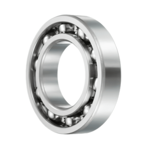
Een asttolerantie voor een lagerstoel wordt gekozen uit het ISO 286 limits-and-fits-systeem, en het is een beslissing over belasting en rotatie, niet een blinde tafel opzoeken De Universiteit van Texas in Austin's referentie op ISO 286 tolerantiekwaliteiten en -passen legt de afkorting uit: een letter stelt de positie van de tolerantieband in ten opzichte van de nominale maat en een getal stelt de breedte ervan in, dus een schacht gemaakt naar “k5” in één winkel valt in een lager dat ergens anders is gemaakt.
Welke klasse je kiest volgt eerst één vraag: welke ring draait, en onder welke belasting De standaard (ANSI/ABMA 7) frames van de American Bearing Manufacturers Association passen bij de selectie rond het type en de omvang van de lagerbelasting. Daarom kan dezelfde nominale diameter een lichtdoorgang of een stevige interferentie vereisen. De Lager-zit Fit Selector vertrekt van die vraag.
| Kenmerk/voorwaarde | Typische schachtklasse | Waarom |
|---|---|---|
| Roterende binnenring, normale belasting | k5 /m6 (lichte interferentie) | Stopt de binnenste ring kruipend en fretting op de zitting |
| Roterende binnenring, zware/schokbelasting | m6 /n6 (steviger) | Hogere belasting heeft meer interferentie nodig om vast te houden |
| Stationaire belasting op binnenring | h6 /g6 (opruiming) | Maakt eenvoudige montage mogelijk; ring probeert niet te kruipen |
| Algemene vrije diameter | h7/IT8 | Geen passend lager; kostengedreven |
Begin met roterende ring + belasting en bevestig vervolgens aan de hand van de montagetafels van uw lagermaker en ISO 286. De interferentie is hier slechts een paar micron, ongeveer 0,002-0,010 mm, ruim binnen de grondjournaalmogelijkheden.
Waarom het ertoe doet: de pasvorm verkeerd krijgen is een storingsmodus in het leerboek. Lageringenieurs merken op dat een stoel die een paar micron te strak is, de interne speling eruit knijpt en het lager door hitte vastgrijpt; een paar micron te los en de ring kruipt, gaat open en faalt vroeg. Dit zijn geen randgevallen, het zijn de meest voorkomende vermijdbare schachtfouten waar machinisten naar vragen. (Voor hoe slijpen deze banden vasthoudt, zie onze opmerking over CNC-bewerkingstoleranties.)
Stel je een winkel voor die een versleten motoras opnieuw heeft geschaafd en, omdat hij een “-fit wilde, gericht op het strakke uiteinde van de band, een paar micron extra interferentie op de lagerstoel. Het lager drukte netjes aan, maar op de teststandaard was het binnen enkele minuten heet: de extra interferentie had de interne speling van het lager naar nul gedrukt, dus de rolelementen begonnen zich te binden en warmte te genereren. Door de volgende as terug te trekken naar een standaard m6-fit, werd deze vastgezet. Dat is precies wat de montagetafel codeert, strakker is niet veiliger, het interferentievenster is slechts een paar micron breed en overschieten aan de hoge kant mislukt net zo zeker als een losse stoel die kruipt.
Belangrijkste afhaalmaaltijden: kies eerst de pasvorm uit roterende ring + belasting en verifieer vervolgens de microns. Het interferentievenster voor een perspassing is slechts een paar µm breed.
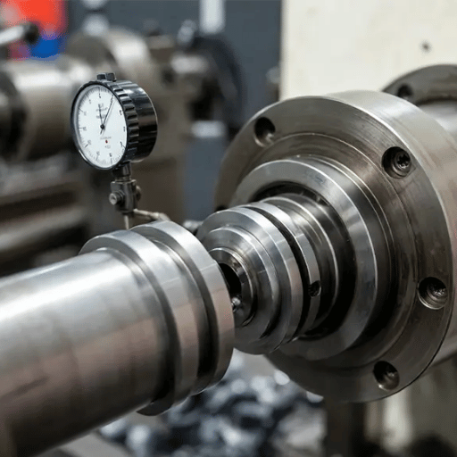
Uitloop is hoe ver een oppervlak wiebelt als de as om zijn ware as draait, gelezen als Total Indicator Reading (TIR). Op een motoras is dit meestal het make-or-break-nummer: lagertappen op een kwaliteitsas worden gewoonlijk vastgehouden op ongeveer ≤0,01 mm TIR, en losse uitloop verschijnt direct als trillingen en lagerslijtage. Portland State University's Ontwerp voor Fit referentie definieert de totale uitloop als de volledige indicatorbeweging (FIM) van een wijzerplaat terwijl het onderdeel draait, en merkt op dat uitloop op een schouder in feite een loodrechtheidsregeling is.
Uitloop wordt bij de machine geregeld en afgetikt Veruit de grootste hendel is het bewerken van de as tussen centra: de middelste gaten worden het gegeven voor elke bewerking, dus de tappen, schouders en afdichtingsoppervlakken delen allemaal één rotatieas in plaats van een spanklapfout te erven.
De kolom van Modern Machine Shop aan TIR versus concentriciteit spanningen controleren op verschillende punten langs het kenmerk, omdat een enkele meting een taps toelopende of gelobde toestand verbergt. Om te verifiëren zit de as op V-blokken (of terug tussen de middelpunten) en wordt een wijzerplaatindicator langs elk oppervlak gesleept terwijl deze wordt gerold.
“Een van de meest voorkomende bronnen van ronding en uitloopfouten bij cilindrisch slijpen zijn de centra in uw onderdelen.”
United Grinding technisch team
Dat inzicht is het inzicht dat de meeste shoppers missen: de kwaliteit van het middengat weegt vaak zwaarder dan het specificatieblad van de grinder. Een versleten of gedingeerd middengat introduceert opnieuw uitloop, hoe goed de machine ook is. Daarom worden ervaren winkels opnieuw gesneden of rondgedraaid voordat ze worden gemalen. Werken tussen centra geeft elk journaal één gemeenschappelijke as, dus de haalbare uitloop wordt beperkt door de kwaliteit van de middelpunten en de slijper in plaats van door een spankfout, en het doel zelf komt van het lager en de loopsnelheid, geverifieerd door uw kant in plaats van door een algemeen getal.
Belangrijkste afhaalmaaltijden: bescherm het gegeven (middens), verwijs er naar elk functioneel oppervlak en controleer TIR op meerdere punten, niet één keer.
Rechtheid is de vormcontrole die ervoor zorgt dat de as van een lange as niet buigt, en die het moeilijkst vast te houden is op slanke delen. Als ruwe regel geldt dat zodra de lengte-diameterverhouding van een as voorbij ongeveer 10-15 stijgt, deze onder zijn eigen snijkrachten van het snijgereedschap afbuigt, zodat de middelste afwerking te groot of gebogen is. Machinistische referenties zoals Machineshandboek addresseer dit met vaste rust en volgersrust die het werkstuk tijdens het draaien ondersteunen; voor zeer lange assen met een kleine diameter, centerless slijpende zijstappen geheel afbuiging Voor delicate precisieassen met een kleine diameter, Zwitserse CNC-bewerking ondersteunt de bar direct bij de snede.
Vaak wel, binnen de perken In de praktijk zet je de as op V-blokken, rol je hem om de hoge plek te vinden, en druk je daar in, itererend naar nul. Maar er is een val die de spec-table-geleiders missen: het rechttrekken van de terugvering is tijdsafhankelijk, dus een schacht die recht tot op 0,05 mm wordt gedrukt, kan de komende dagen meetbaar ontspannen voordat deze stabiliseert.
Een peer-reviewed onderzoek in Machines (2022) ontdekte dat het buigen en rechttrekken van de slanke as blijft ontspannen na het lossen; één exemplaar werd onmiddellijk acceptabel gemeten, maar dreef tien dagen later over een lengte van 760 mm naar 0,261 mm. De les: laat een gestrekte as bezinken vóór de laatste inspectie, anders riskeer je een valse acceptatie. De geometrie zelf wordt gedefinieerd door normen, het Amerikaanse NIST-rapport tolerantienormen vergelijken (NISTIR 4744) merkt op dat de rechtheid van een as wordt begrensd door een cilindrische zone (volgens ISO 1101:2017 en ASME Y14.5), en niet slechts door twee parallelle lijnen.
Zwaar vervormde of geharde assen kunnen verder gaan dan het koud rechttrekken; gepatenteerde productiemethoden zoals rechttrekken van koppelassen (US 5253499A) laat zien waarom de fabricage van de aandrijfas recht wordt en toen balansen, de volgorde is belangrijk, omdat een rechttrekkende pass massa verschuift en een eerder evenwicht ongedaan maakt.
Belangrijkste afhaalmaaltijden: steun slanke schachten tijdens het snijden, richt op V-blokken high-spot-first, en laat het deel ontspannen voordat u rechtheid certificeert.
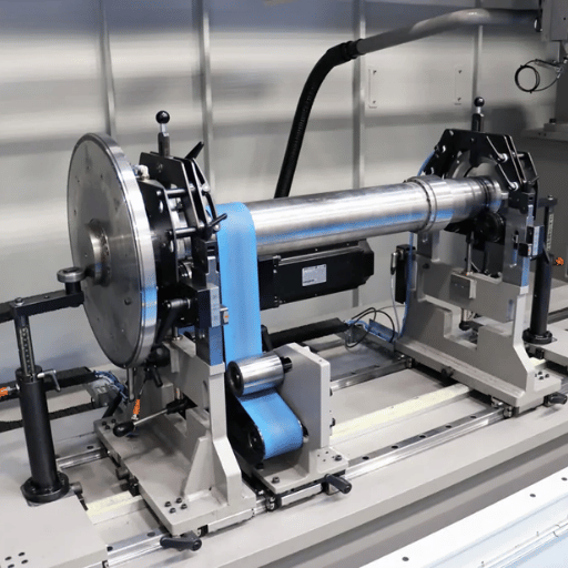
Balanceren regelt hoe de voltooide, roterende as massa verdeelt, zodat deze draait zonder zichzelf en zijn lagers uit elkaar te trillen. Balanceren wordt geregeld door ISO 21940-11 (die ISO 1940-1 vervangt): het kent een balanskwaliteitsklasse toe, G6.3 dekt de meeste algemene elektromotoren, pompen, ventilatoren en ventilatoren, terwijl G2.5 gereserveerd is voor motorrotoren met hogere snelheid of hogere precisie en aandrijvingen van werktuigmachines, en G16 dekt grovere apparatuur, en de toegestane resterende onbalans krimpt naarmate de servicesnelheid stijgt, omdat toegestane onbalans een functie is van rotormassa en maximale bedrijfssnelheid. Texas A&M's rotorial tutorial houdt de rotorgroep vrij selecteren van de balanskwaliteit van de stijve rotor.
Nee, en anders aannemen is een veel voorkomende over-spec. Een langzame, symmetrische, stijve rotor voldoet vaak direct aan zijn kwaliteit van de slijpmachine, en als je hem in evenwicht brengt, worden er kosten zonder voordeel toegevoegd. Twee waarschuwingen uit het trillingsveld scherpen de beslissing aan voordat je een as aan een balans met twee vlakken vastlegt, bijvoorbeeld op G2.5.
Ten eerste is een 1×-RPM trilling niet altijd veroorzaakt door onbalans, verkeerde uitlijning, een gebogen as of losheid produceren dezelfde signatuur, dus bevestig de oorzaak voordat u in evenwicht bent. Ten tweede hangt de juiste aanpak af van de rotorklasse: a rigid rotor is gebalanceerd bij lage snelheid (ISO 21940-11), maar een as die boven de eerste buigmodus loopt, is een flexibel rotor en heeft behoefte aan hoge snelheidsbalancering ISO 21940-31 verbindt zelfs gevoeligheid aan hoe dicht een resonantie zit aan bedrijfssnelheid, een rang alleen garandeert geen soepele loop.
Denk aan een onderhoudsteam dat een pompmotor drie keer trok om hem opnieuw in evenwicht te brengen, op jacht naar een hardnekkige 1×-RPM trilling Elke balanceerpas was prima op de machine gemeten, maar de trilling kwam weer in gebruik Maar de boosdoener was helemaal niet uit balans, een zachte voet en lichte verkeerde uitlijning van de koppeling leverden dezelfde 1×-RPM signatuur op Een laser uitlijningscontrole, niet een andere balanceerpas, heeft het uiteindelijk gewist Daarom is de veldregel om de bron van een 1×-RPM trilling te bevestigen voordat wordt aangenomen dat de as zelf moet worden gebalanceerd, en waarom een langzame, symmetrische stijve rotor die al aan zijn kwaliteit voldoet vaak met rust gelaten.
| Grade | Typische toepassing | Planes |
|---|---|---|
| G2.5 | Motorrotoren met hogere snelheid en hogere precisie, aandrijvingen van werktuigmachines | 1 of 2 |
| G6.3 | Algemene elektromotoren, pompwaaiers, ventilatoren, blowers | 1 of 2 |
| G16 | Grovere aandrijfcomponenten, landbouwaandrijvingen | 1 |
Cijfers volgens ISO 21940-11; eenvlak past bij korte rotoren, tweevlak is nodig naarmate de lengte en snelheid stijgen.
Belangrijkste afhaalmaaltijden: stel de balansgraad in op basis van snelheid en rotorklasse, bevestig dat een trilling feitelijk uit balans is en betaal niet voor het balanceren van twee vlakken die een langzame stijve rotor niet nodig heeft.
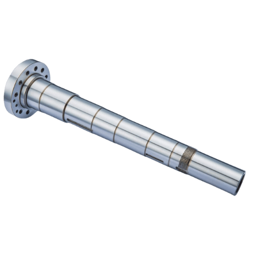
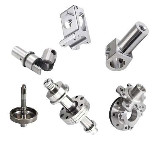
Vóór de kenmerken helpt het om de as zelf te plaatsen. De meeste motor- en aandrijfassen vallen in negen terugkerende typen, elk gedefinieerd door één dominant kenmerk dat de manier waarop het wordt bewerkt aandrijft.
| Type as | Definiërende functie | Typisch gebruik |
|---|---|---|
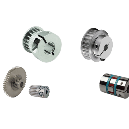
| Gesleuteld | Gefreesde spiebaan + sleutel | Pompen, motoren, katrollen (matig koppel) |
| Gespleten | Meerdere lengtegroeven | Versnellingsbakken, aandrijflijnen (hoog koppel, gelijkmatige belasting) |
| Hol | Centrale boring | Robotica, lucht- en ruimtevaart (lage traagheid, draadgeleiding) |
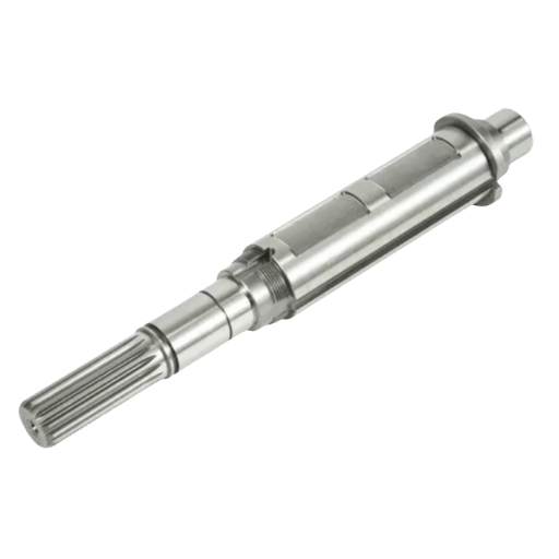
| Stapte | Meerdere diameters + schouders | Multi-lager motor/versnellingsbakassen |
| Taps toelopend | Geleidelijke diameterverandering | Zelfsluitende naven, vliegwielen |
| Schroefdraad | Externe/interne threads | Actuators, lineaire aandrijvingen, klemmen |
| Rotor (motor) | Draagt de rotorkern/laminaties | Elektrische motorkernen, hogesnelheidsplicht |
| Spindel | Zeer nauwkeurig roterend onderdeel | Werktuigmachines, instrumenten (zeer lage uitloop) |
| Aandrijving /lijn | Lange, koppeloverbrengende overspanning | Vermogenstransmissie over afstand |
De meeste motorassen dragen een paar standaardkenmerken, spiebanen en spiebanen om koppel over te brengen, holle boringen om gewicht te besparen of bedrading te leiden, schroefdraad of taps toelopende uiteinden om componenten te monteren, en getrapte diameters voor lagerzittingen en schouders Sleutelwegen en spiebanen worden gefreesd (EDM snijdt ze in reeds geharde assen via het afvoerproces dat wordt gebruikt in patenten zoals de draadslijpwielmethode, EP 1064116B1); voor deze functies snijdt onze CNC-freeslijn de sleuven waar mogelijk in dezelfde opstelling als het draaien.
📐 Engineering Note-kenmerken zijn vermoeidheidsplaatsen
Vermoeiingsfouten in de roterende as beginnen zelden in het midden van een vlakke diameter; ze beginnen bij stress raisersspiebaanuiteinden, spiewortels, filets en scherpe schouders Geometrie is de ontwerphendel: royale filetstralen (minstens 0,5-1,0 mm) bij schouders, afgeronde spiebaanuiteinden en het vermijden van abrupte sectieveranderingen doen meer voor de levensduur van de as dan nog een hardheidspunt. Behandel spiebanen en spiebanen als vermoeiingskenmerken, niet alleen als koppelkenmerken.
Materiaal volgt de plicht Koolstofstaal 1045 is de economische standaard; gelegeerde staalsoorten 4140 en 4340 zijn de werkpaarden voor beladen assen omdat ze goed warmtebehandelen, inductiegeharde tappen bereiken ongeveer 50.60 HRC aan het oppervlak terwijl de kern taai blijft (gegevenslijsten van technisch staal 4140 tot ongeveer HRC 58 oppervlaktehardheid in de inductiegeharde toestand). Voor corrosiedienst, roestvrij staal bewerking in 416 of 431 wordt enige bewerkbaarheid voor weerstand ingeruild; voor de hoogste sterkte-tot-gewicht titanium- of nikkellegeringen zoals Inconel-handvatlucht- en ruimtevaart- en hogetemperatuurschachten.
| Grade | Sleutel eigenschap | Gebruik het voor |
|---|---|---|
| 1045 koolstofstaal | Economisch, bewerkbaar, lasbaar | Motor- en pompassen voor algemeen gebruik |
| 4140 / 4340 legering | Stoere kern, ~50-60 HRC-inductiegeval | Geladen aandrijfassen, tandwielassen |
| 416 / 431 roestvrij | Corrosieweerstand | Nat, afspoelen, maritieme service |
| Titanium / Inconel | Sterkte-tot-gewicht /hittebestendigheid | Lucht- en ruimtevaart, hogetemperatuurschachten |
Hardheids-/sterktecijfers zijn afhankelijk van de warmtebehandelingsconditie; bevestig dit aan de hand van het molencertificaat voor de specifieke kwaliteit en temperatuur.
Belangrijkste afhaalmaaltijden: kies het cijfer voor gebruik, verhard de tappen voor slijtage en straal de spanningsverhogers, vermoeiingsleven of sterven op spiebanen en filets.
Een motorastekening die machines de eerste keer recht zet, speldt de hele Precision Stack vast, niet alleen de diameters. Elektrische motor-, pomp- en versnellingsbakassen verschillen voornamelijk in welke kenmerken domineren, lager-journaaluitloop voor motoren, afdichting-oppervlakteafwerking en corrosie voor pompen, spie-/tandtandnauwkeurigheid voor versnellingsbakassen, maar de tekenchecklist is hetzelfde. Standaardinstellingen zoals ASME (Y14.5-2018, de huidige GD&T-editie die 2009 verving) en ISO (286 voor pasvormen, 1101 voor vorm) geeft u de taal; de Motoras Tekening Spec Sheet hieronder is wat we vragen kopers te bevestigen voordat u citeert.
Die laatste regel is belangrijker dan kopers verwachten Een “±0,005 mm”-mogelijkheid is alleen betekenisvol met de inspectiemethode en kalibratie erachter, NIST dimensional-metrology guidance behandelt meetonzekerheid als onderdeel van het resultaat, niet als een optioneel QA-detail. Bij onze precisie CNC-bewerking winkel-, draai-, Zwitsers-, cilindrisch slijpen, honen en CMM/FAI-inspectie bevinden zich onder één dak, dus het beste figuur van ±0,005 mm wordt geleverd met het maatrapport dat dit bewijst, voor de specifieke tijdschriften van uw kant, niet als een algemene garantie.
Belangrijkste afhaalmaaltijden: specificeer datums, pasvormen, uitloop, rechtheid, balansgraad, filets en de inspectiemethode. Een tekening met de naam van het bewijs is een tekening die nauwkeurig citeert.
De vraag naar precisieschachten groeit en wordt steeds krapper. Marktonderzoeksbureaus schatten de markt voor precisiebewerking op ongeveer 123.134 miljard dollar in 2025-2026, geraamd op 224 tot 229 miljard dollar in 2033-2034 op een CAGR van 6,6 tot 8,1%, waarbij het segment slijpmachines bijna 6,2 miljard dollar bedraagt en deze stijgt, beschouwen deze als geschatte bereiken, niet als precieze cijfers. Elektrificatie is de duidelijkste vraagstimulator: analisten koppelen de stijgende vraag naar CNC rechtstreeks aan de productie van elektrische voertuigen en motorcomponenten.
Waar je op moet plannen is de verschuiving naar gesloten-lus slijpen. In-proces en na-proces meting (en steeds meer AI-ondersteunde adaptieve controle) nu meten van de journal als het is geslepen en correct in real time, het aanscherpen van herhaalbaarheid op precies de lager-zit kenmerken deze gids gaat Automatisering patenten zoals de rol-gebaseerde richtmethode die de richttijd berekent op basis van de roldiameter, het motortoerental en de overbrengingsverhouding (WO 2020062362A1) wijs op dezelfde manier, van het oordeel van de operator tot gemeten, zelfcorrigerende cellen. Als u schachten zoekt voor een programma voor 2026-2027, vraag dan aan leveranciers wat zij tijdens het proces meten en hoe zij dit documenteren; die mogelijkheid, en niet de nominale prijs, is wat consistente tijdschriften zal scheiden van drijvende tijdschriften.
Belangrijkste afhaalmaaltijden: precisie en volume stijgen beide naarmate de vraag naar EV-motoren toeneemt, bevoordelen leveranciers met in-procesmeting en gedocumenteerde gesloten-luscontrole.
Schachtbewerking is het geordende proces waarbij een metalen staaf in een afgewerkte roterende as wordt gedraaid. Een plano wordt ruw gedraaid tussen de middelpunten om de diameters en de middengatgegevens in te stellen, gefreesd voor spiebanen of platte vlakken en vervolgens met hitte behandeld voor hardheid. Na het uitharden worden de lagertappen afgewerkt voor uiteindelijke grootte, rondheid en oppervlakteafwerking, omdat slijpen een strakkere band vasthoudt dan het draaien van blik. Inspectie, CMM-afmetingen, uitloop op V-blokken en soms dynamisch balanceren, sluit vervolgens de lus vóór het schachtschip.
De materiaalkeuze hangt af van de belasting en het milieu. 1045 koolstofstaal is de economische standaard voor assen voor algemeen gebruik; 4140- en 4340-legeringsstaal hebben de voorkeur voor belaste assen omdat ze warmtebehandelen tot een taaie kern met een inductiegeharde tap rond 50-60 HRC. Voor corrosieservice wordt 416 of 431 roestvrij staal gebruikt; voor de beste sterkte-gewicht- of hoge-temperatuurbelasting worden titanium- en nikkellegeringen zoals Inconel gekozen ondanks hogere kosten en hardere bewerking.
Een aanvaardbare uitloop hangt af van het lager en de snelheid, maar de lagertappen op een kwaliteitsmotoras worden gewoonlijk op ongeveer 0,01 mm (ongeveer 0,0004 inch) gehouden, de totale indicatorwaarde is strakker, en precisieassen lopen daar ruim onder. Het aantal wordt bepaald door het lager en de loopsnelheid, en het is alleen betekenisvol als het wordt gemeten tussen middelpunten of op V-blokken op verschillende punten langs elke tap, en niet op basis van een enkele meting.
Binnen de perken Milde bochten kunnen op V-blokken (high-spot first) met een druk recht worden gezet, en versleten tappen kunnen soms ondermaats worden omgedraaid of worden opgebouwd en opnieuw worden omgedraaid, zwaar vervormde of verharde assen worden vaak beter vervangen Altijd een rechtgetrokken schacht laten bezinken voor de eindcontrole.
Een getrapte as wordt ruw gedraaid tussen de middelpunten om maalmateriaal op elke tap achter te laten, met warmte behandeld, waarna elke getrapte diameter cilindrisch wordt geslepen tot de ISO 286-fitklasse. Het slijpen tussen dezelfde middelpunten houdt alle stappen concentrisch en de uitloop wordt stap voor stap tegen de referentieas gecontroleerd.
Nr Een langzame, symmetrische starre rotor voldoet vaak aan zijn ISO 21940-11-rang zonder een afzonderlijke balanceringsstap Balanceren loont als snelheid en lengte stijgen, en onthoud dat een 1×-RPM trilling kan komen van verkeerde uitlijning of een gebogen as, niet alleen uit balans.
Grote assen worden beperkt door draaibankschommel, slijplengte tussen de middelpunten en capaciteit van de winkelkraan in plaats van door de bewerkingsmethode zelf. Lange, slanke assen zijn eigenlijk het moeilijkere geval, ze buigen af onder hun eigen snijbelasting en hebben stabiele of volgsteunen nodig plus zorgvuldige controle van de rechtheid, ongeacht de diameter.
Noodzaak precisie motorassen machinaal bewerkt en geïnspecteerd?
Le Creator draait, maalt, hones, en CMM-inspecteert aangepaste schachten onder één dak, met het dimensionale rapport dat de tolerantie bewijst.
De tolerantie-, uitloop- en balanscijfers in deze gids zijn samengesteld op basis van ISO- en ASME-normen, NIST- en universitaire metrologiereferenties, peer-reviewed slijp- en richtstudies en bronnen voor machinale bewerking en handel, kruislings gecontroleerd aan de hand van onze eigen motoras werk, draaien, Zwitsers, cilindrisch slijpen, honen en CMM/FAI-inspectie bij Le Creator (ISO 9001:2015 /IATF 16949 /AS9100D /ISO 13485). Waar een waarde systeemafhankelijk is (een pasvorm, een balansgraad, een capaciteit van ±0,0005 mm), zeggen we dat als universeel getal.