

Ondersteunende, professionele, klantgerichte service
Van prototypes tot productie op volledige schaal, wij hebben u gedekt.


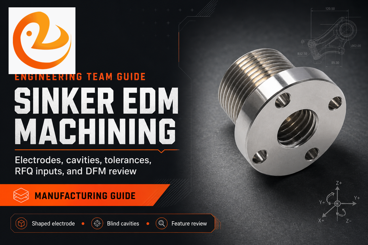
Leer hoe zinklood EDM-bewerking werkt, wanneer u het over draad EDM- of CNC-frezen moet gebruiken, hoe elektroden de toleranties beïnvloeden en wat u vóór RFQ moet voorbereiden.
Sinker EDM-bewerking is een contactloze productiemethode voor het vormen van blinde holtes, ribben, spieën en verzonken kenmerken in geleidende metalen onderdelen In tegenstelling tot een snijgereedschap erodeert een gevormde elektrode materiaal met gecontroleerde elektrische ontladingen, zodat het proces kan werken op harde materialen en delicate geometrieën die moeilijk te bewerken zijn door conventionele bewerking alleen.
Gebruik zinklood EDM wanneer de functie wordt gedefinieerd door een interne vorm, niet door een open gereedschapspad. Het is een precisiebewerkingsoptie voor geleidend materiaal, maar het is geen snelkoppeling voor elke holte of zak.
Gebruik zinklood EDM wanneer de functie wordt gedefinieerd door een interne vorm, niet door een open gereedschapspad.
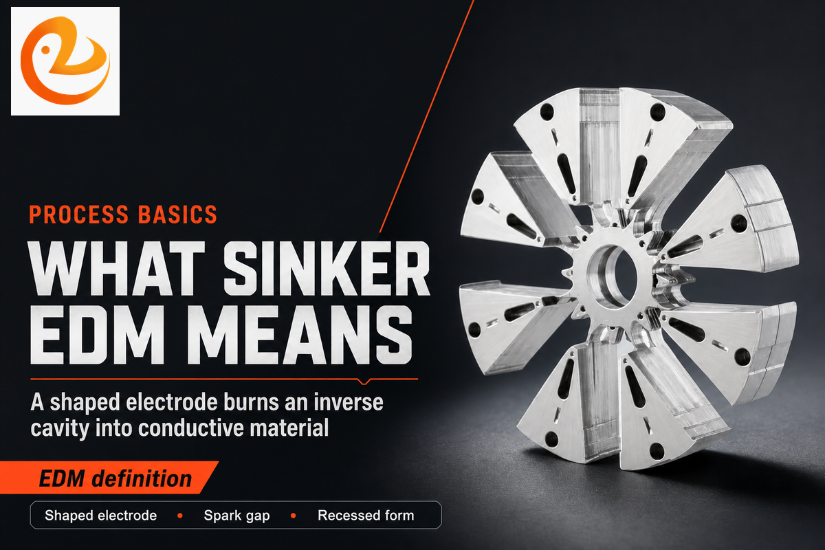
Sinker EDM is een type EDM dat een gevormde elektrode gebruikt om de omgekeerde vorm van die elektrode in een werkstuk te branden. Het wordt ook wel ram EDM, plunge EDM, holte EDM of matrijszinkende EDM genoemd. Het bevindt zich in de machinebedrijfsfamilie voor elektrische ontlading naast draad-EDM- en EDM-boringen. ANSI B11.27 beschrijft elektroontladingsmachines als inclusief machinewerktuigen voor het zinken, boren en draadsnijden, waardoor de procesfamilie duidelijk gescheiden blijft van frezen en draaien.
In praktische winkeltaal is de EDM-elektrode het gereedschap en het werkstuk het onderdeel. De twee hoeven elkaar nooit aan te raken. Tijdens de verbranding houdt de zinklood-EDM-machine een gecontroleerde vonkbrug tussen hen in, stuurt gepulseerde ontladingsenergie door een diëlektrische vloeistof en verwijdert kleine hoeveelheden metaal totdat het bewerkingsdoel van de geprogrammeerde holte is bereikt.
Die definitie is van belang voor technische teams omdat zinklood EDM de geometrie anders gebruikt dan CNC-frezen. Frezen hebben gereedschapstoegang, fluitsterkte, spaanafvoer en hoekradiusruimte nodig. Daarentegen kan een zinkloodelektrode een verzonken vorm in het onderdeel dragen zolang het materiaal elektriciteit geleidt, de elektrode kan worden gemaakt en het spoelpad vuil kan verwijderen.
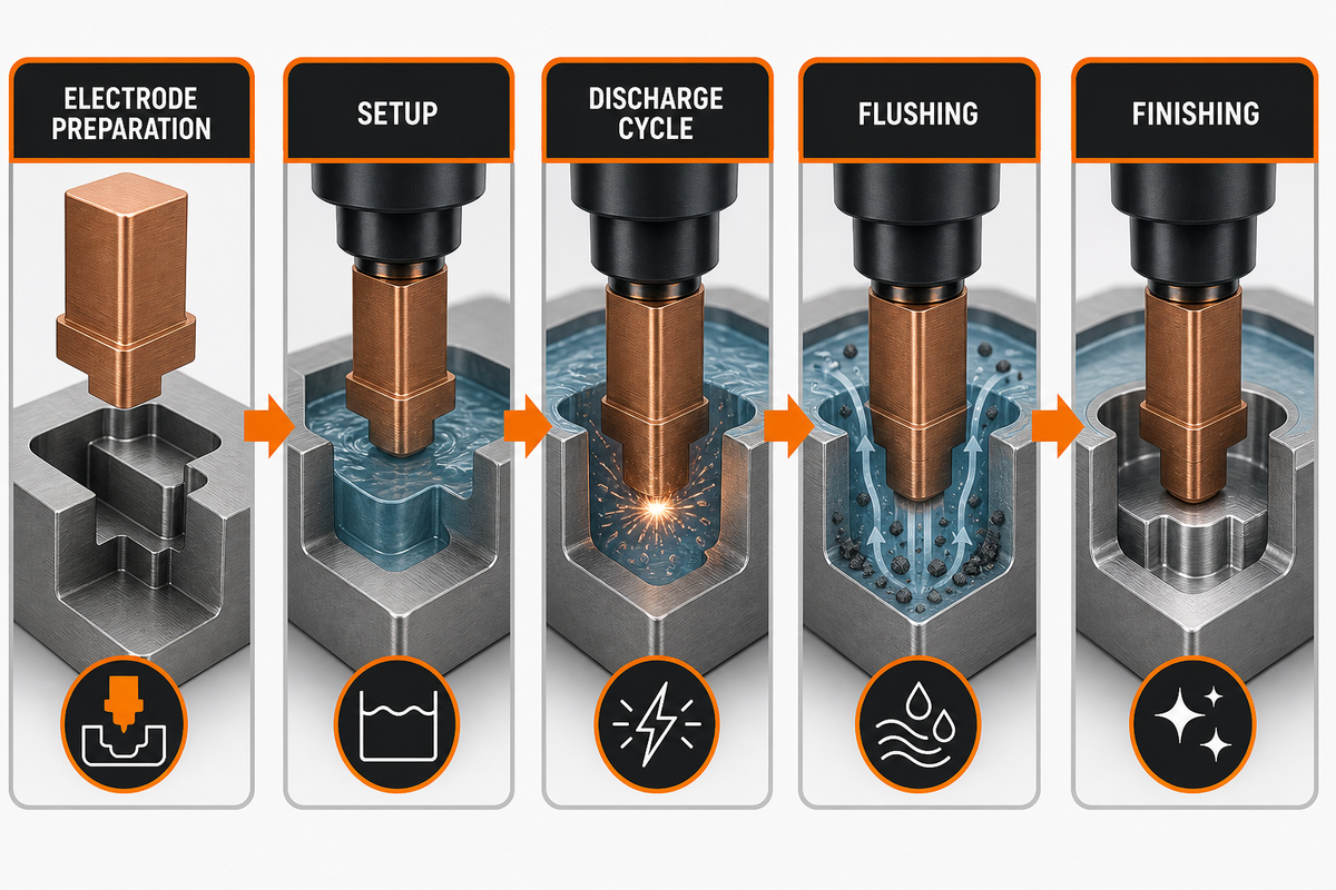
EDM werkt door herhaalde elektrische ontladingen over een smalle kloof. In het zinklood-EDM-proces beweegt de gevormde elektrode zich onder servobesturing naar het werkstuk, terwijl diëlektrische vloeistof de zone afkoelt en geërodeerde deeltjes wegvoert. Dit produceert een omgekeerde holte in plaats van een door een chip gesneden oppervlak.
Vergeleken met ruwe bewerking door een snijder, is het proces traag, maar het kan functies creëren die extreme snijdlengte, geklets, gereedschapsbreuk of een split-part ontwerp zouden forceren Voor vorminzetstukken, geharde gereedschapsstaalholten en smalle ribben is die afweging vaak rationeel.
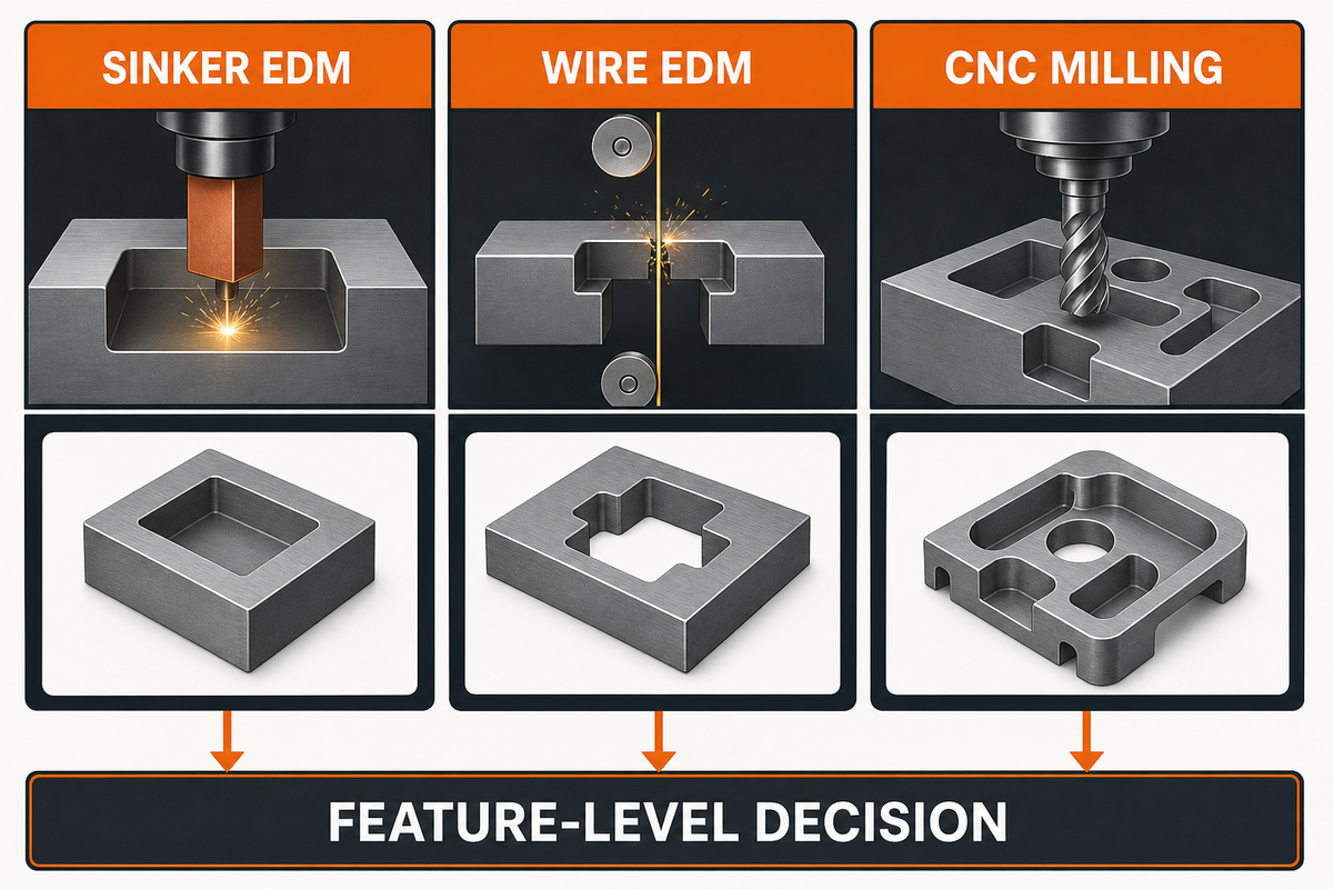
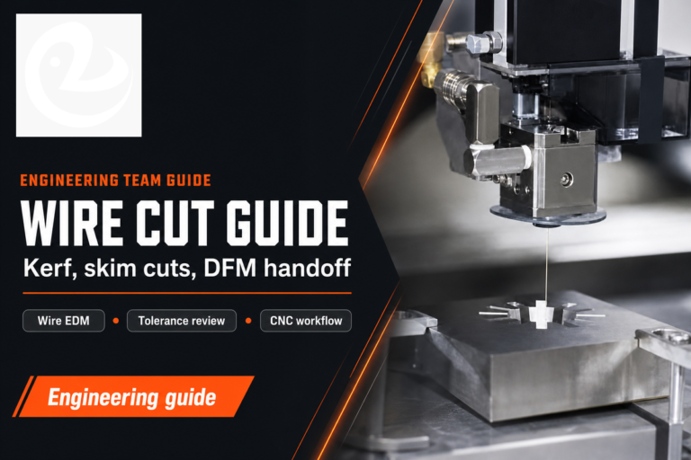
Kiezen tussen zinklood EDM en draad EDM is vooral een geometrievraag. Draad EDM, met inbegrip van draad-gesneden EDM, voert een bewegende draad door het deel en is sterk voor doorgaande profielen Voor doorgesneden profielen die de draadroute nodig hebben, Le Creator's draad EDM-service is de relevantere procespagina Sinker EDM wordt gebruikt voor blinde zakken, holtes en 3D inbouwvormen. CNC frezen is nog steeds sneller voor open zakken, platte gezichten en bulk voorraadverwijdering.
| Productieroute | Beste pasvorm | Kijkpunt | Typisch technisch gebruik |
|---|---|---|---|
| Sinker EDM | Blinde holtes, ribben, interne vormen, scherp verzonken detail | Elektrodekosten, spoelen, slijtagevergoeding, bewerkingstijd | Schimmelholtes, matrijskenmerken, interne splines, hardmetalen details |
| Draad EDM | Door profielen en 2D contouren | Heeft een startgat of een open snijpad door het onderdeel nodig | Ponsen, platen, tandwielen, profielen en extrusiematrijzen |
| CNC frezen | Open geometrie waarbij EDM niet nodig is voor volumeverwijdering | Gereedschapsbereik, snijdiameter en onderdeelhardheid kunnen de toegang beperken | Ruwe voorraadverwijdering, open zakken, geboorde gaten en datumkenmerken |
Vaak wordt de sterkste route gecombineerd: CNC voorbewerken eerst, zinklood EDM voor de moeilijk bereikbare holte, en polijsten of inspectie daarna Behandel zinklood EDM vs draad EDM als een beslissing op feature-niveau in plaats van een voorkeur op plantniveau.
Gebruik de onderstaande matrix als voorbeeld voor het tekenen van signalen, niet voor universele capaciteitsbeloften. Het doel ervan is om aan te tonen welk feature-type een productiebeoordeling moet activeren en welke informatie met de RFQ mee moet reizen.
| Eigenschapstype | Voorbeeld tekensignaal | Waarschijnlijk route | RFQ-risico ter verduidelijking |
|---|---|---|---|
| Blinde holte | 12 mm tot 35 mm holtediepte met een gesloten bodem | CNC voorbewerken plus zinklood EDM-afwerking | Bodemstraal en branddieptekaart |
| Diepe rib | 0,4 mm tot 1,0 mm ribbreedte op een malinzetstuk | Sinker EDM met getrapte elektroden | Elektrodefragiliteit en spoelpad |
| Verzonken scherpe hoek | 0,2 mm binnenradiusnoot na verharding | Sinker EDM finishing pass | Hoekslijtage en inspectietoegang |
| Interne spline | Interne vorm met 18 tanden of 24 tanden zonder toegang tot de aansnijding | Vorm elektrodeverbranding | Verificatiemethode voor tandprofielen |
| Gehard inzetstuk | HRC 48 tot HRC 62 werkstukconditie | EDM na verharding | Datumverschuiving en meting na verbranding |
| Afdichtoppervlak | Ra 0,8 um tot Ra 1,6 um noot op een functioneel gezicht | Afwerking burn plus eventueel polijsten | Oppervlakteruwheid en herschikte laagregel |
| Microzak | 2 mm tot 5 mm zakbreedte zonder snijspeling | Sinker EDM als elektrode kan worden geïnspecteerd | Slijtage van elektroderanden en afkeurcriteria |
| Open zak | 20 mm bij 50 mm open ruimte in bewerkbare voorraad | CNC frezen eerst | Of EDM waarde toevoegt die verder gaat dan ruwe bewerking |
| Productieherhaling | 10 delen, 50 delen of 200 delen met herhaalde holtegeometrie | Levensschema van de elektrode plus inspectie van het eerste stuk | Elektrodevervangingsinterval en meetrapport |
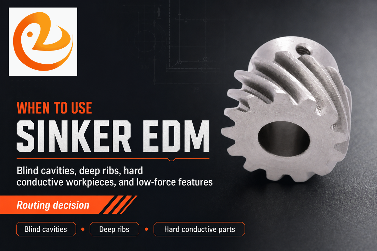
Kies zinklood EDM wanneer de geometrie, materiaal- of krachtgevoeligheid een conventioneel snijgereedschap onbetrouwbaar maakt. Het is het sterkst als de tekening vraagt om een verzonken kenmerk met een strakke interne vorm, een diepe rib, een harde geleidend werkstuk, of een oppervlak dat na het uitharden moet worden geproduceerd.
Net zo belangrijk is de tegenregel Kies geen zinklood EDM voor eenvoudige open zakken, grote holtes met platte bodem in eenvoudig te bewerken aluminium, niet-geleidende kunststoffen of functies waarbij een standaard CNC-gereedschap het onderdeel sneller kan afwerken. In die gevallen kan zinklood EDM de elektrodekosten toevoegen zonder technische waarde toe te voegen.
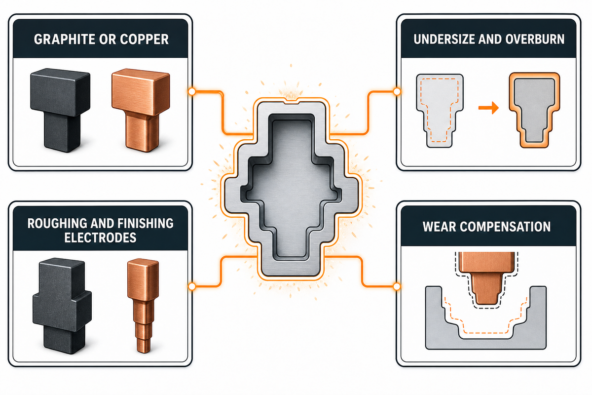
Elektrodeontwerp is het risico dat de meeste niet-EDM-teams onderschatten. Sinker EDM-machines kunnen alleen reproduceren wat de elektrode-, instel- en ontladingsparameters kunnen volhouden. Als de elektrode te delicaat, te moeilijk te inspecteren of slecht gecompenseerd is voor overbrand, zal de uiteindelijke holte die fout erven.
| Elektrodebesluit | Engineering impact | RFQ-notitie om op te nemen |
|---|---|---|
| Grafiet of koper | Grafiet is gebruikelijk voor snelheid en slijtagegedrag; koper kan in geselecteerde gevallen fijne details en afwerkingsdoelen ondersteunen. | Vraag of elektrodemateriaal de doorlooptijd, kosten of haalbare afwerking verandert. |
| Ondermaats en overbranden | De elektrode moet volgens plan kleiner zijn dan de doelholte spark gap-toeslag. | Deel de dimensies die functiekritisch zijn, niet alleen het nominale CAD-model. |
| Ruw- en afwerkingselektroden | Een ruwe elektrode verwijdert materiaal; een afwerkingselektrode beschermt de oppervlakteafwerking en de uiteindelijke grootte. | Geef aan of cosmetische, afdichtings- of vermoeiingsoppervlakken een afwerkingspas nodig hebben. |
| Draag compensatie | Hoge ribben, scherpe hoeken en diepe brandwonden kunnen de elektrode ongelijkmatig dragen. | Roep diepe secties, minimale stralen en inspectiegegevens vroegtijdig op. |
Voor een technische ontgrendeling mag u de elektrode niet als een detail voor alleen winkels behandelen. Neem het holtemodel, de toegang tot de elektrode, de minimale interne straal, de polijstvergoeding en het inspectieplan op in dezelfde productiebeoordeling. Dat is waar bewerkingsoplossingen voorspelbaarder worden.

Sinker EDM heeft een elektrisch geleidend materiaal. Veel voorkomende werkstukfamilies zijn onder meer gehard gereedschapsstaal, roestvrij staal, titanium, wolfraamcarbide, Inconel, koper en aluminium. Materiaalhardheid blokkeert het EDM-proces niet op dezelfde manier waarop het traditionele bewerking blokkeert, maar thermisch gedrag, toegang tot spoelen en afwerkingseisen doen er nog steeds toe.
Niet-geleidende materialen liggen buiten de normale procesgrens. De meeste kunststoffen, het meeste glas en veel standaardkeramiek hebben een andere bewerkingsmethode nodig, tenzij ze geleidend worden gemaakt door een speciale formulering of bevestigingsstrategie. Zelfs met geleidende metalen zijn grote open zakken meestal goedkoper tot ruw door CNC vóór elke bewerkingsstap met elektrische ontlading.
Eigenschapslimieten zijn ook praktisch in plaats van absoluut. Smalle diepe ribben kunnen mogelijk zijn, maar de elektrode kan kwetsbaar worden. Zeer fijne texturen kunnen mogelijk zijn, maar de bewerkingstijd en afwerkingspassen kunnen stijgen. Harde inzetstukken kunnen mogelijk zijn, maar inspectie moet bewijzen dat de holtevorm stabiel is na de verbranding.
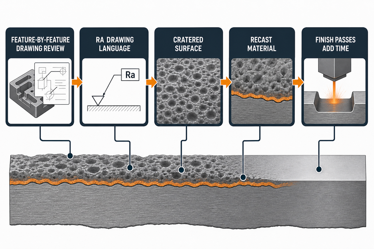
Hoe nauwkeurig is zinklood EDM? nauwkeurigheid hangt af van het kenmerk, de elektrodegeometrie, de vonkbrugregeling, diëlektrisch spoelen, pulsenergie, afwerkingsgangen en inspectiemethode Dekentolerantienummers zijn zwakker dan een tekenbeoordeling per functie.
ASME B46.1 definieert oppervlaktetextuurterminologie zoals ruwheid, golving en lay, daarom moeten RFQ's oppervlakteafwerking vermelden in tekentaal zoals Ra in plaats van in vage cosmetische termen. Handelsreferenties op EDMed-oppervlakken beschrijven ook een bekraterd oppervlak en herschikt materiaal gevormd door het thermische proces.
Als het onderdeel vermoeidheidsgevoelig, corrosiegevoelig, afdichtingskritisch of onderworpen is aan certificering na de bewerking, vermeld dan of verwijdering van de herschikte laag, polijsten, etsen of oppervlakte-inspectie vereist is. Laat die beslissing pas liggen nadat de holte is verbrand.
Oppervlakteafwerking en tolerantie zijn gekoppeld maar niet identiek Fijne afwerkingspassen kunnen Ra en dimensionale herhaalbaarheid verbeteren, maar toch voegen ze tijd toe en hebben ze mogelijk een aparte elektrode nodig Ruwende brandwonden kunnen sneller zijn, maar toch kunnen ze een oppervlakteconditie achterlaten die moet worden gepolijst of andere nabewerking. Op de tekening moet staan welke oppervlakken er toe doen.
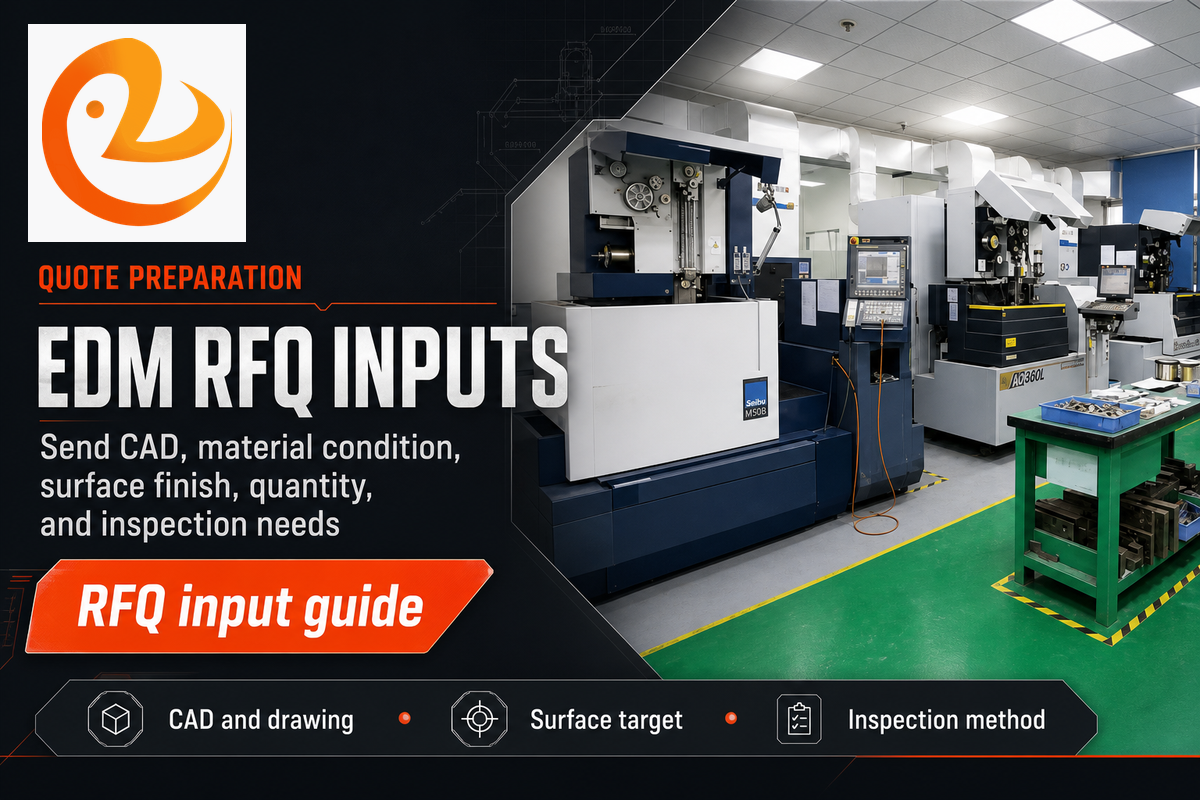
De EDM-kosten van zinklood worden minder bepaald door het kernmateriaal en meer door het aantal elektroden, de diepte van de holte, het aantal kenmerken en het doel oppervlakteafwerking, inspectielast, nabewerking en totale brandtijd Kleine onderdelen kunnen nog steeds duur zijn als de elektrode complex is en de afwerkingseis streng is.
Voor onderdelen die CNC-ruwwerk combineren met EDM-achtige afwerking, De CNC-bewerkingsservice van Le Creator kan CAD-, materiaal-, afwerkings- en inspectie-eisen beoordelen als onderdeel van de productieoverdracht. Gebruik die beoordeling voor routing en DFM-uitlijning; ga niet uit van een zinkloodspecifieke mogelijkheid totdat de geometrie en vereisten zijn gecontroleerd aan de hand van het beschikbare procesplan.
Een handig tekenpakket kan een holtediepte van 18 mm, een ribbreedte van 0,6 mm, een minimale binnenradius van 0,3 mm, een Ra-afwerkingsdoel van 1,6 um, een materiaalconditie van HRC 54, een inspectievenster van 4 uur, 25 delen in de eerste partij, 100 delen in de herhaling lot, en een beoordelingsdoel voor het eerste artikel van 2 dagen. Het kan ook een gegevensprobleem van 0,05 mm markeren, een polijstdoel van 5 um, een CMM-slot van 1 uur, een herhaalordervenster van 30 dagen of een armatuurlimiet van 2 kg. Dit zijn voorbeeldvelden om betere citaten te vragen, geen vaste proceslimieten.
| RFQ-signaal | Voorbeeldwaarde | Implicatie beoordelen |
|---|---|---|
| Holtediepte | 18 mm | Controleer het bereik van de elektrode en de toegang tot spoelen. |
| Ribbreedte | 0,6 mm | Beoordeel de kwetsbaarheid van grafiet of koperelektroden. |
| Binnenradius | 0,3 mm | Plan overbrandvergoeding en inspectietoegang. |
| Oppervlaktedoel | Ra 1,6 um | Bepaal of een afwerkingselektrode nodig is. |
| Materiaalconditie | HRC54 | Bevestig de route na het harden. |
| Eerste lot | 25 onderdelen | Instellen eerste-stuk inspectie timing. |
| Herhaal veel | 100 onderdelen | Schema elektrode slijtage controles. |
| Datum zorg | 0,05 mm | Bind EDM-opstelling terug aan tekendata. |
| Armatuurmassa | 2 kg | Controleer de limieten voor handling en tankopstelling. |
| RFQ-ingang | Waarom het de quote verandert | Wat te verzenden |
|---|---|---|
| 3D CAD en 2D tekening | Het model definieert vorm; de tekening definieert wat er gemeten moet worden. | STEP-bestand plus PDF met datums en kritische opmerkingen. |
| Materiaal en warmtebehandelingsconditie | Geleidbaarheid, hardheid en thermische respons beïnvloeden de brandstrategie. | Legering, temperatuur, hardheidsbereik en eventuele certificeringsbehoeften. |
| Holtediepte en minimale straal | Diepe smalle kenmerken verhogen het risico op elektroden, spoelen en slijtage. | Dieptekaart, minimale binnenradius en ontoegankelijke hoeken. |
| Oppervlakteafwerking en herschikte eis | Fijne Ra-doelen en verwijderingseisen voegen passes of polijsten toe. | Ra-doel, cosmetische zones, afdichtingszones en aantekeningen van de herschikte laag. |
| Hoeveelheid en inspectiemethode | Prototype-, brug- en productiehoeveelheden hebben verschillende elektrode- en QC-plannen nodig. | Hoeveelheid, partijsplitsing, CMM-behoeften, optische controles en rapportageformaat. |
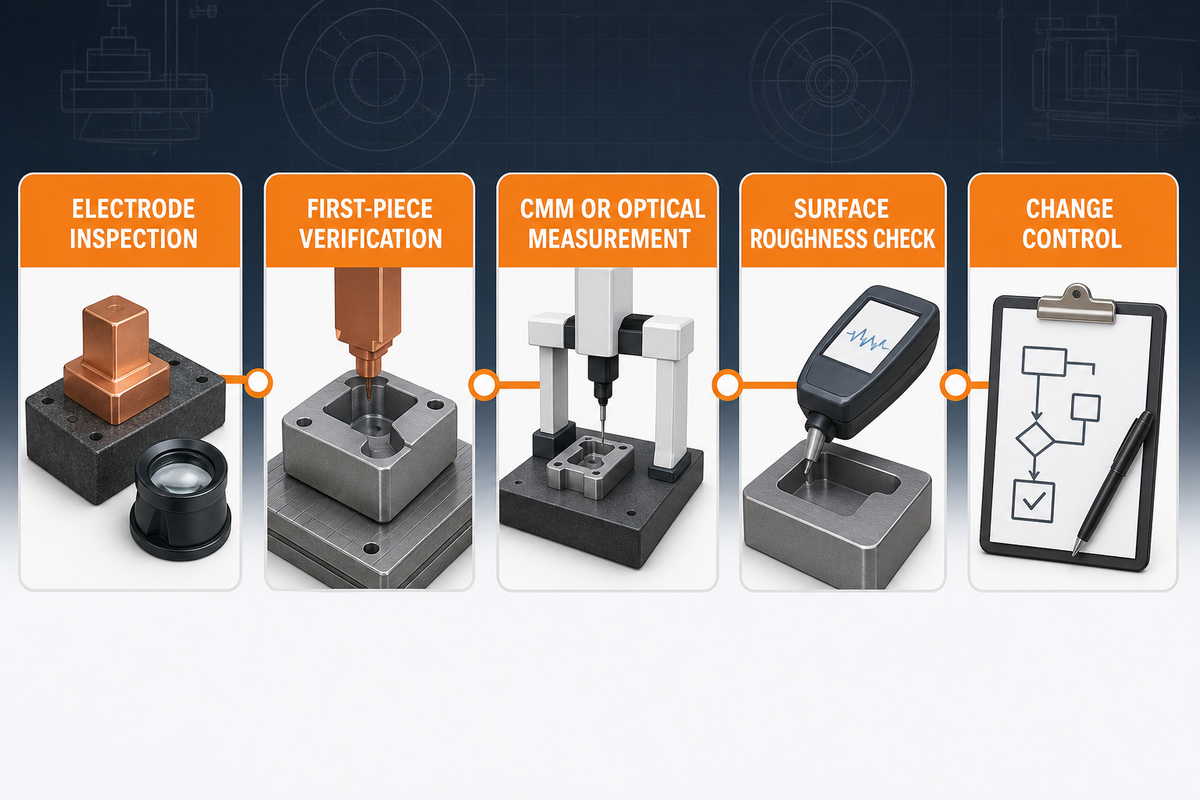
Kwaliteitscontrole voor zinklood EDM begint vóór de verbranding Voordat de eerste holte wordt geaccepteerd, moet de winkel de elektrode, het werkvasthouden, de offsets, de datumoverdracht en de meetmethode bevestigen. Dit geldt vooral wanneer de EDM-holte past op een gegoten oppervlak, inzetstuk, afdichting of schuifcomponent.
Inspectietaal moet gebonden blijven aan de tekening. In plaats van te vragen of de EDM-mogelijkheden een hoge nauwkeurigheid hebben, definiëren“ de exacte oppervlakken, toleranties, datums en rapporten die zullen bewijzen dat het onderdeel kan worden gebruikt.
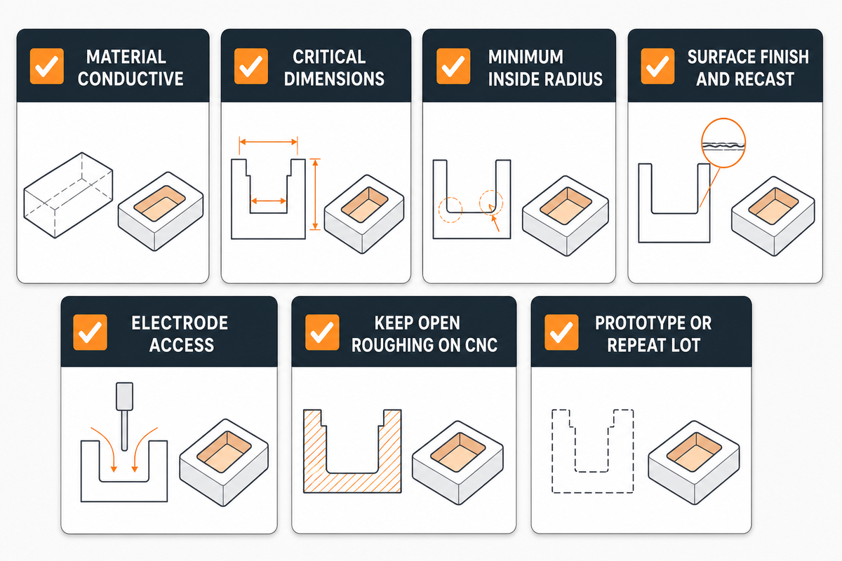
Voordat een RFQ wordt vrijgegeven, moeten technische teams scheiden wat EDM moet zijn van wat CNC gefreesd kan blijven. Dit verlaagt de kosten, houdt de EDM-methoden gericht op de harde functies en geeft de leverancier een schoner beslissingstraject.
Sterke DFM-pakketten geven de leverancier toestemming om de juiste volgorde te kiezen: CNC-bewerking voor het verwijderen van ruw materiaal, zinklood EDM voor de verzonken geometrie, draad EDM en zinklood EDM alleen waar elk proces past, en inspectie op de punten die de functie beschermen Wanneer de tekenset klaar is, gebruik dan Le Creator's contactpagina om het RFQ-pakket met CAD, tekennotities en inspectievereisten te verzenden.
Het artikel behandelt zinklood EDM als een technische routeringsbeslissing, niet als een generiek EDM-overzicht. De feiten van de openbare site van Le Creator worden alleen gebruikt voor de merk- en CNC-servicecontext; zinkloodspecifieke toleranties, doorlooptijden en procesmogelijkheden moeten worden bevestigd aan de hand van de daadwerkelijke onderdeelgeometrie en het RFQ-pakket.