

Service de soutien, professionnel et axé sur le client
Des prototypes à la production à grande échelle, nous avons ce qu'il vous faut.


Découvrez comment fonctionne l'usinage EDM par plomb, quand l'utiliser sur le fraisage EDM ou CNC par fil, comment les électrodes affectent les tolérances et quoi préparer avant la RFQ.
L'usinage EDM par évier est une méthode de fabrication sans contact pour façonner des cavités borgnes, des nervures, des cannelures et des éléments en retrait dans des pièces métalliques conductrices Contrairement à un outil de coupe, une électrode façonnée érode le matériau avec des décharges électriques contrôlées, de sorte que le processus peut fonctionner sur des matériaux durs et des géométries délicates difficiles à usiner par le seul usinage conventionnel.
Utilisez l'EDM de plomb lorsque la caractéristique est définie par une forme interne, pas par un chemin d'outil ouvert C'est une option d'usinage de précision pour le matériau conducteur, mais ce n'est pas un raccourci pour chaque cavité ou poche.
Utilisez l'EDM de plomb lorsque la fonctionnalité est définie par une forme interne et non par un chemin d'outil ouvert.
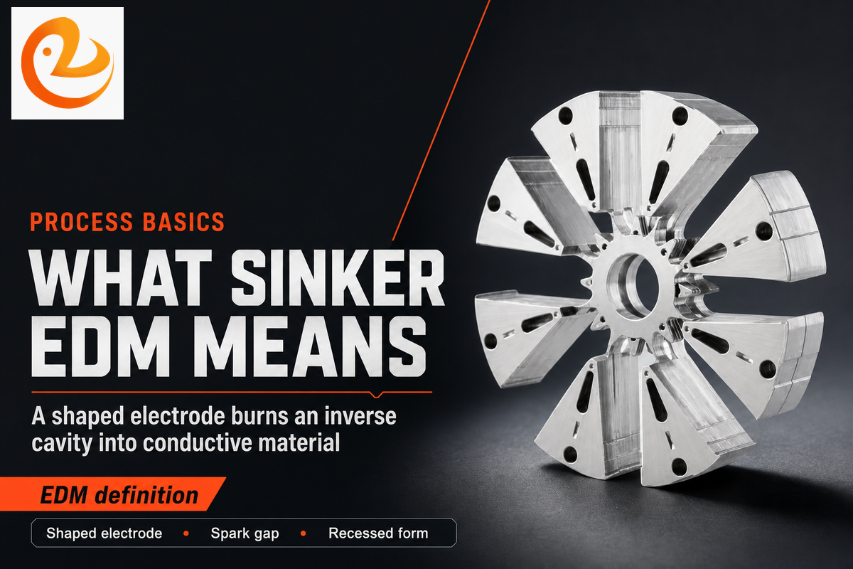
Le Sinker EDM est un type d'EDM qui utilise une électrode façonnée pour brûler la forme inverse de cette électrode dans une pièce. Il est également appelé pilon EDM, plongée EDM, cavité EDM ou matrice d'enfoncement EDM. Il se trouve à l'intérieur de la famille d'usinage par décharge électrique aux côtés du fil EDM et du perçage EDM. ANSI B11.27 décrit les machines à électrodécharge comme incluant les machines-outils de fonçage, de perçage et de coupe de fil, ce qui maintient la famille de processus clairement séparée du fraisage et du tournage.
Dans le langage pratique de l'atelier, l'électrode EDM est l'outil et la pièce est la pièce Les deux n'ont jamais besoin de toucher Pendant la combustion, la machine EDM à plomb garde un éclateur contrôlé entre eux, envoie de l'énergie de décharge pulsée à travers un fluide diélectrique et élimine d'infimes quantités de métal jusqu'à ce que la cible d'usinage à cavité programmée soit atteinte.
Cette définition est importante pour les équipes d'ingénierie car l'EDM à plomb utilise la géométrie différemment du fraisage CNC. Les fraises ont besoin d'un accès à l'outil, de la résistance de la cannelure, de l'évacuation des copeaux et de l'espace du rayon d'angle. En revanche, une électrode à plomb peut transporter une forme évidée dans la pièce tant que le matériau conduit l'électricité, que l'électrode peut être fabriquée et que le chemin de rinçage peut éliminer les débris.
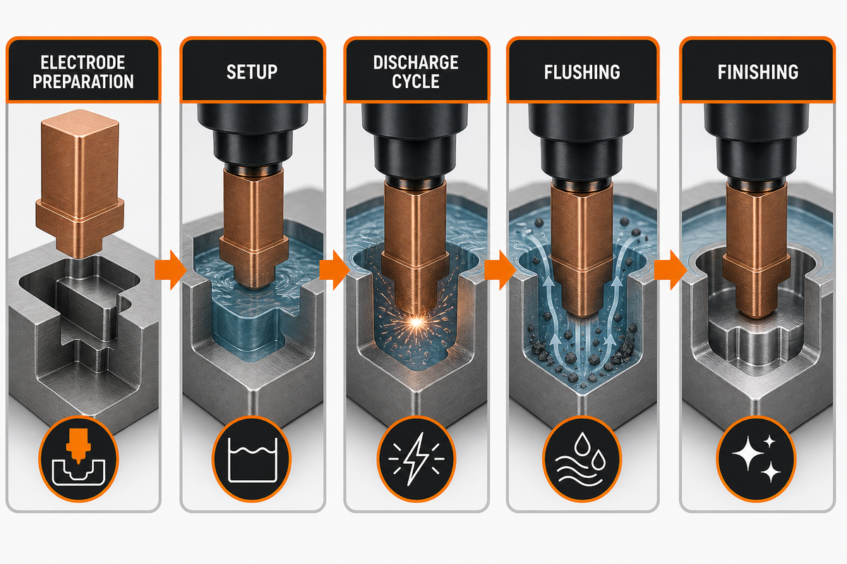
L'EDM fonctionne en effectuant des décharges électriques répétées à travers un écart étroit. Dans le processus EDM du plomb, l'électrode façonnée avance vers la pièce sous servocommande, tandis que le fluide diélectrique refroidit la zone et éloigne les particules érodées. Cela produit une cavité inverse plutôt qu'une surface découpée en copeaux.
Comparé à l'usinage grossier par une fraise, le processus est lent, mais il peut créer des caractéristiques qui forceraient une longueur extrême de la fraise, un broutage, une rupture de l'outil ou une conception en partie fendue. Pour les inserts de moule, les cavités en acier à outils trempées et les nervures étroites, ce compromis est souvent rationnel.
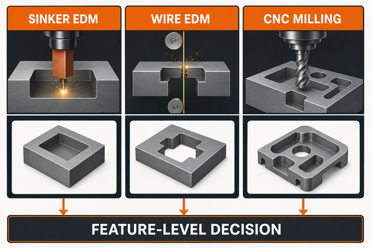
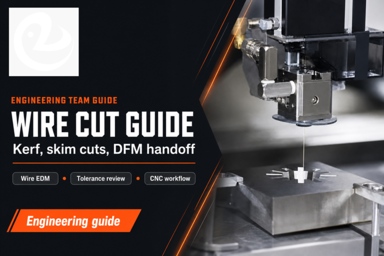
Choisir entre l'EDM à plomb et l'EDM à fil est principalement une question de géométrie. ÉDM filaire, [TRADUCTION], y compris l'EDM coupé par fil, alimente un fil mobile à travers la pièce et est solide pour les profils traversants Pour les profils traversants qui ont besoin de la route du fil, celle de Le Creator service EDM filaire est la page de processus la plus pertinente Sinker EDM est utilisé pour les poches aveugles, les cavités et les formes en retrait 3 D. Fraisage CNC est encore plus rapide pour les poches ouvertes, les faces plates et l'enlèvement de stock en vrac.
| Voie de fabrication | Meilleur ajustement | Point de surveillance | Utilisation typique de l'ingénierie |
|---|---|---|---|
| Édm de sinker | Cavités aveugles, nervures, formes internes, détail en retrait pointu | Coût de l'électrode, rinçage, résistance à l'usure, temps d'usinage | Cavités de moule, caractéristiques de matrice, cannelures internes, détails en métal dur |
| ÉDM filaire | À travers des profils et des contours 2D | Nécessite un trou de départ ou un chemin de coupe ouvert à travers la pièce | Poinçons, plaques, engrenages, profilés et filières d'extrusion |
| Fraisage CNC | Géométrie ouverte où l'EDM n'est pas nécessaire pour la suppression du volume | La portée de l'outil, le diamètre de la fraise et la dureté des pièces peuvent limiter l'accès | Enlèvement brut des stocks, poches ouvertes, trous percés et caractéristiques de référence |
Souvent, la voie la plus solide est combinée : ébauche CNC d'abord, EDM plomb pour la cavité difficile à atteindre, et polissage ou inspection après Traiter l'EDM plomb vs EDM fil comme une décision au niveau des caractéristiques plutôt qu'une préférence au niveau de l'usine.
Utilisez la matrice ci-dessous comme exemple de signaux de dessin, et non comme promesses de capacités universelles Son but est de montrer quel type de fonctionnalité doit déclencher un examen de fabrication et quelles informations doivent voyager avec la RFQ.
| Type de caractéristique | Exemple de signal de dessin | Itinéraire probable | Risque RFQ à clarifier |
|---|---|---|---|
| Cavité aveugle | Profondeur de cavité de 12 mm à 35 mm avec fond fermé | ébauche CNC plus finition EDM plomb | Carte du rayon inférieur et de la profondeur de combustion |
| Côte profonde | Largeur de nervure de 0,4 mm à 1,0 mm sur un insert de moule | ÉDM de sinker avec électrodes étagées | Fragilité des électrodes et chemin de rinçage |
| Coin tranchant encastré | Note de rayon intérieur de 0,2 mm après durcissement | Passe finale du Sinker EDM | Usure des coins et accès à l'inspection |
| Spline interne | Forme interne à 18 dents ou 24 dents sans accès broche | Brûlure d'électrode de forme | Méthode de vérification du profil dentaire |
| Insert durci | État de la pièce HRC 48 à HRC 62 | EDM après durcissement | Décalage de référence et mesure après combustion |
| Surface d'étanchéité | Ra 0,8 um à Ra 1,6 um note sur un visage fonctionnel | Brûlure de finition plus polissage possible | Rugosité de surface et règle de la couche refondue |
| Micro poche | Largeur de poche de 2 mm à 5 mm sans jeu de coupe | ÉDM de l'enfonceur si l'électrode peut être inspectée | Critères d'usure et de rejet des bords des électrodes |
| Poche ouverte | Zone ouverte de 20 mm sur 50 mm en stock usinable | Fraisage CNC d'abord | Si l'EDM ajoute de la valeur au-delà de l'usinage grossier |
| Répétition de production | 10 parties, 50 parties ou 200 parties avec géométrie de cavité répétée | Plan de vie des électrodes plus inspection de première pièce | Intervalle de remplacement des électrodes et rapport de mesure |
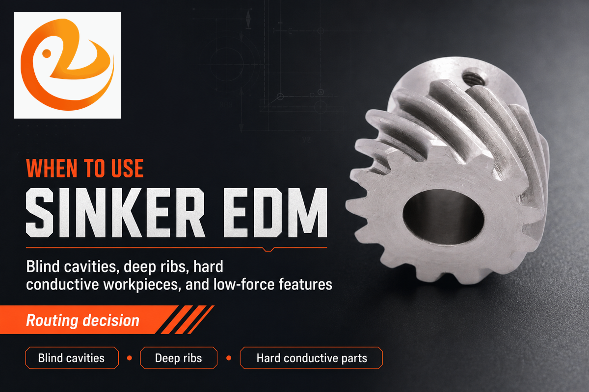
Choisissez l'EDM de plomb lorsque la géométrie, la sensibilité du matériau ou de la force rend un outil de coupe conventionnel peu fiable C'est plus fort lorsque le dessin demande un élément en retrait avec une forme interne serrée, une nervure profonde, un dur pièce conductrice, 1, ou une surface qui doit être produite après durcissement.
Tout aussi importante est la contre-règle Ne choisissez pas l'EDM de plomb pour les poches ouvertes simples, les grandes cavités à fond plat en aluminium facile à usiner, les plastiques non conducteurs ou les caractéristiques où un outil CNC standard peut finir la pièce plus rapidement Dans ces cas, l'EDM de plomb peut ajouter le coût de l'électrode sans ajouter de valeur technique.
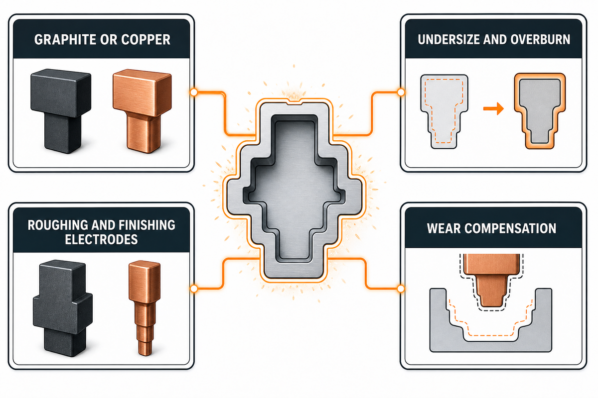
La conception des électrodes est le risque que la plupart des équipes non EDM sous-estiment Les machines Sinker EDM ne peuvent reproduire que ce que les paramètres d'électrode, de configuration et de décharge peuvent supporter Si l'électrode est trop délicate, trop difficile à inspecter ou mal compensée pour la surbrûlure, la cavité finale héritera de cette erreur.
| Décision d'électrode | Impact d'ingénierie | Note RFQ à inclure |
|---|---|---|
| Graphite ou cuivre | Le graphite est courant pour la vitesse et le comportement à l'usure ; le cuivre peut prendre en charge des détails fins et finir les cibles dans des cas sélectionnés. | Demandez si le matériau de l'électrode modifie le délai d'exécution, le coût ou la finition réalisable. |
| Sous-dimensionnement et surbrûlure | L'électrode doit être plus petite que la cavité cible d'un point prévu allocation d'éclateur. | Partagez les dimensions qui sont critiques pour la fonction, pas seulement le modèle CAO nominal. |
| Électrodes d'ébauche et de finition | Une électrode rugueuse enlève le matériau ; une électrode de finition protège la finition de surface et la taille finale. | Indiquez si les surfaces cosmétiques, d'étanchéité ou de fatigue nécessitent une passe de finition. |
| Compensation de port | De hautes côtes, des coins pointus et des brûlures profondes peuvent user l'électrode de manière inégale. | Appelez tôt les sections profondes, les rayons minimum et les données d'inspection. |
Pour une version technique, ne traitez pas l'électrode comme un détail réservé à l'atelier Incluez le modèle de cavité, l'accès à l'électrode, le rayon interne minimum, la tolérance de polissage et le plan d'inspection dans la même revue de fabrication C'est là que les solutions d'usinage deviennent plus prévisibles.

Sinker EDM a besoin d'un matériau électriquement conducteur. Les familles de pièces courantes comprennent l'acier à outils trempé, l'acier inoxydable, le titane, le carbure de tungstène, l'Inconel, le cuivre et l'aluminium La dureté des matériaux ne bloque pas le processus EDM de la même manière qu'elle bloque l'usinage traditionnel, mais le comportement thermique, l'accès au rinçage et les exigences de finition comptent toujours.
Les matériaux non conducteurs se situent en dehors des limites normales du processus. La plupart des plastiques, la plupart du verre et de nombreuses céramiques standard nécessitent une autre méthode d'usinage, à moins qu'ils ne soient rendus conducteurs par une formulation spéciale ou une stratégie de fixation. Même avec des métaux conducteurs, les grandes poches ouvertes sont généralement moins chères à ébaucher par CNC avant toute étape d'usinage par décharge électrique.
Les limites de caractéristiques sont également pratiques plutôt qu'absolues Des nervures profondes étroites peuvent être possibles, mais l'électrode peut devenir fragile Des textures très fines peuvent être possibles, mais le temps d'usinage et les passes de finition peuvent augmenter Les inserts durs peuvent être possibles, mais l'inspection doit prouver que la forme de la cavité est stable après la brûlure.
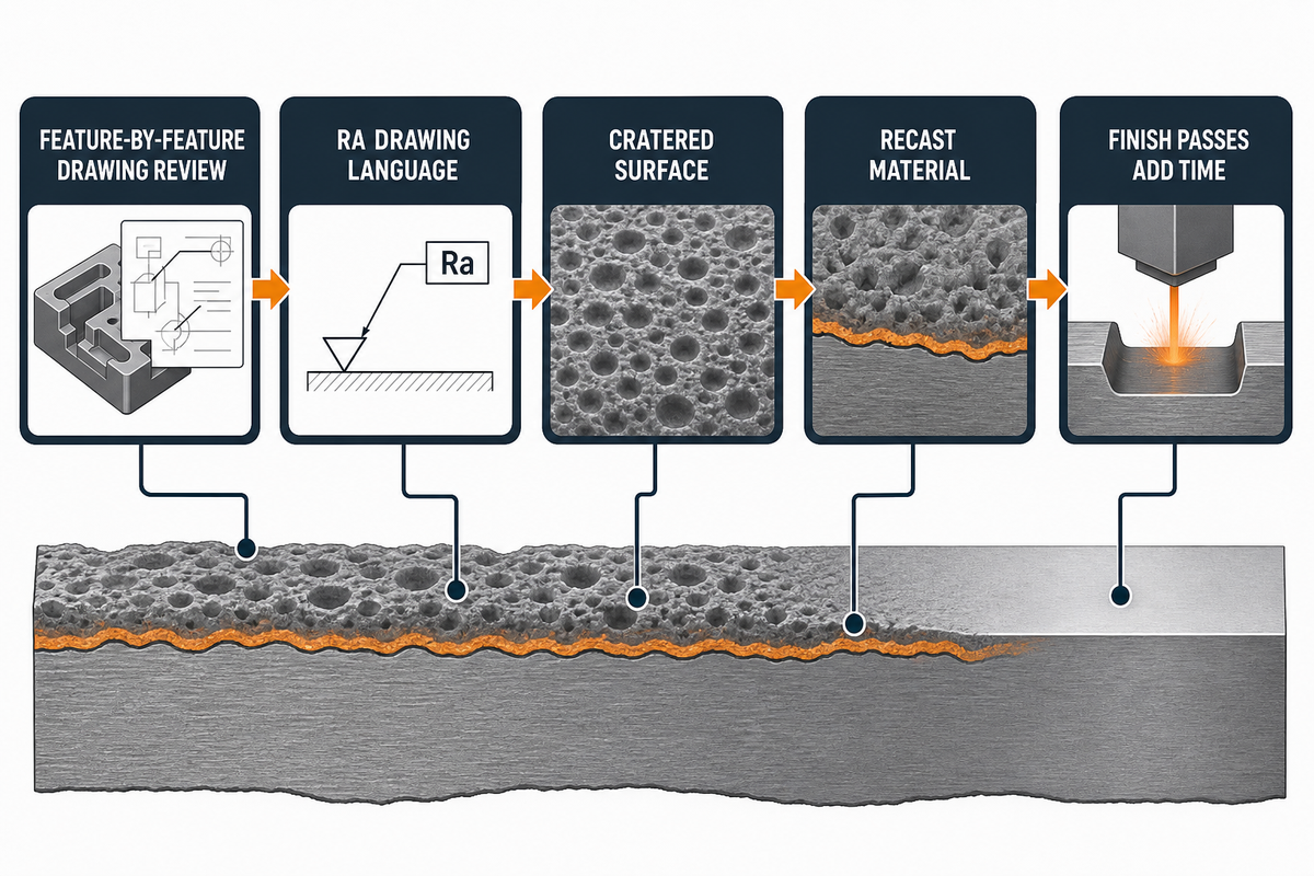
Quelle est la précision de l'EDM du plomb ? la précision dépend de la caractéristique, de la géométrie de l'électrode, du contrôle de l'éclateur, du rinçage diélectrique, de l'énergie des impulsions, des passes de finition et de la méthode d'inspection Les nombres de tolérance de couverture sont plus faibles qu'une revue de dessin caractéristique par caractéristique.
ASME B46.1 définit la terminologie de la texture de surface telle que la rugosité, l'ondulation et la pose, c'est pourquoi les RFQ devraient énoncer la finition de surface dans un langage de dessin tel que Ra plutôt qu'en termes cosmétiques vagues Les références commerciales sur les surfaces EDMed décrivent également une surface cratérisée et un matériau refondu formé par le processus thermique.
Si la pièce est sensible à la fatigue, sensible à la corrosion, critique pour l'étanchéité ou soumise à une certification post-usinage, indiquez si le retrait de la couche refondue, le polissage, la gravure ou l'inspection de surface ne laissez cette décision qu'après la combustion de la cavité.
La finition de surface et la tolérance sont liées mais pas identiques Les passes de finition fine peuvent améliorer Ra et la répétabilité dimensionnelle, mais elles ajoutent du temps et peuvent nécessiter une électrode séparée Les brûlures brutales peuvent être plus rapides, mais elles peuvent laisser un état de surface nécessitant un polissage ou un autre post-traitement. Le dessin doit indiquer quelles surfaces comptent.
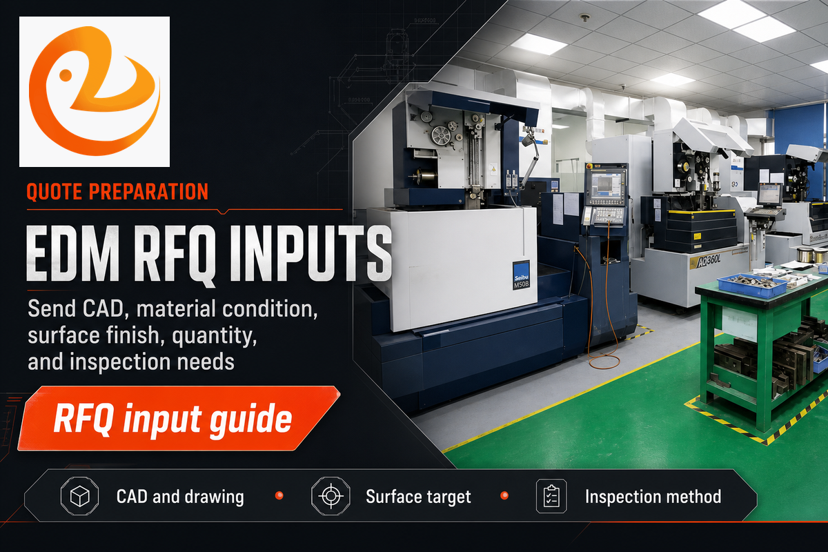
Le coût de l'EDM du sinker dépend moins du matériau principal que du nombre d'électrodes, de la profondeur de la cavité, du nombre de caractéristiques et de la cible finition de surface, charge d'inspection, post-traitement et temps de combustion total Les petites pièces peuvent toujours être coûteuses si l'électrode est complexe et que l'exigence de finition est stricte.
Pour les pièces qui combinent l'ébauche CNC avec la finition de style EDM, Service d'usinage CNC de Le Creator peut examiner les exigences de CAO, de matériel, de finition et d'inspection dans le cadre du transfert de fabrication Utilisez cet examen pour le routage et l'alignement DFM ; ne supposez pas une capacité spécifique au plomb tant que la géométrie et les exigences ne sont pas vérifiées par rapport au plan de processus disponible.
Un emballage de dessin utile peut identifier une profondeur de cavité de 18 mm, une largeur de nervure de 0,6 mm, un rayon intérieur minimum de 0,3 mm, une cible de finition Ra de 1,6 um, l'état du matériau HRC 54, 4 heures de fenêtre d'inspection, 25 parties dans le premier lot, 100 parties dans le lot répété et un objectif d'examen du premier article de 2 jours. Il peut également signaler un problème de référence de 0,05 mm, une cible de polissage de 5 um, un emplacement CMM d'une heure, une fenêtre d'ordre répété de 30 jours ou une limite de fixation de 2 kg. Ce sont des champs d'exemple pour inciter à mieux citer, et non des limites de processus fixes.
| Signal RFQ | Valeur d'exemple | Implication de l'examen |
|---|---|---|
| Profondeur de la cavité | 18 mm | Vérifiez la portée de l'électrode et l'accès au rinçage. |
| Largeur de la côte | 0,6 mm | Revoir la fragilité des électrodes en graphite ou en cuivre. |
| Rayon intérieur | 0,3 mm | Planifier l'indemnité de surbrûlure et l'accès à l'inspection. |
| Cible surfacique | Ra 1,6 um | Décidez si une électrode de finition est nécessaire. |
| État matériel | CDH 54 | Confirmez le routage post-durcissement. |
| Premier lot | 25 parties | Définissez le timing d’inspection de la première pièce. |
| Répétez beaucoup | 100 pièces | Planifiez les contrôles d’usure des électrodes. |
| Préoccupation relative aux données | 0,05 mm | Reliez la configuration EDM aux données de dessin. |
| Masse de fixation | 2 kg | Vérifier les limites de manutention et de configuration des réservoirs. |
| Entrée RFQ | Pourquoi il change le devis | Quoi envoyer |
|---|---|---|
| CAO 3 D et dessin 2D | Le modèle définit la forme ; le dessin définit ce qui doit être mesuré. | fichier STEP plus PDF avec des données et des notes critiques. |
| État matériel et traitement thermique | La conductivité, la dureté et la réponse thermique affectent la stratégie de combustion. | Alliage, trempe, plage de dureté et tout besoin de certification. |
| Profondeur de la cavité et rayon minimum | Des caractéristiques profondes et étroites augmentent les risques d'électrode, de rinçage et d'usure. | Carte de profondeur, rayon intérieur minimum et coins inaccessibles. |
| Exigence de finition de surface et de refonte | Les cibles Fine Ra et les exigences de retrait ajoutent des passes ou du polissage. | Cible Ra, zones cosmétiques, zones de scellement et notes de recast-couche. |
| Quantité et méthode d'inspection | Les quantités de prototype, de pont et de production nécessitent différents plans d'électrodes et de contrôle qualité. | Quantité, répartition des lots, besoins en CMM, contrôles optiques et format de rapport. |
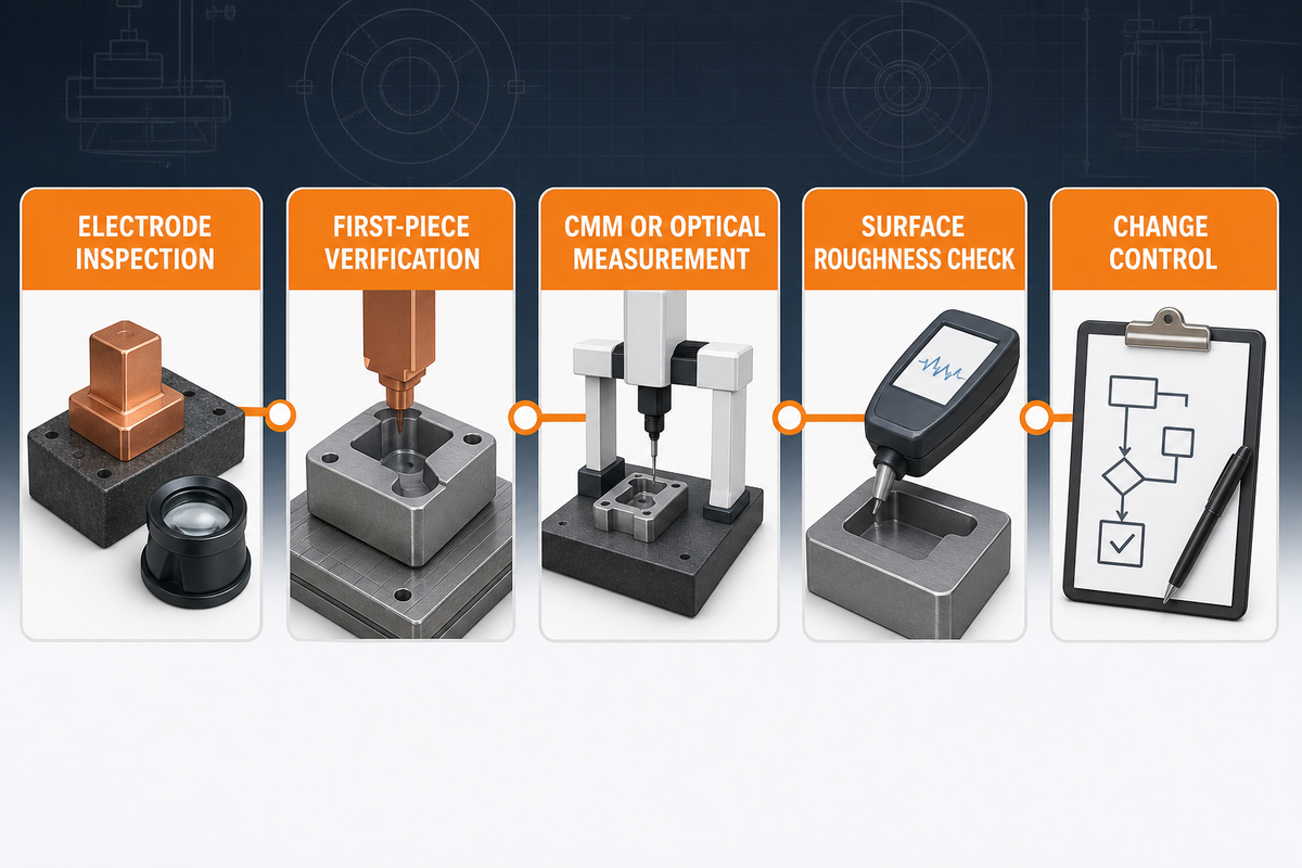
Contrôle de qualité pour le plomb EDM commence avant la combustion Avant d'accepter la première cavité, l'atelier doit confirmer l'électrode, le maintien, les décalages, le transfert de données et la méthode de mesure. Cela est particulièrement vrai lorsque la cavité EDM s'accouple avec une surface moulée, un insert, un joint ou un composant coulissant.
Le langage d'inspection doit rester lié au dessin Au lieu de se demander si les capacités EDM sont de haute précision,“ définit les surfaces exactes, les tolérances, les données et les rapports qui prouveront que la pièce peut être utilisée.
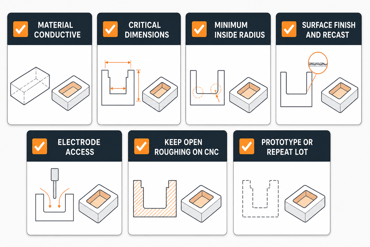
Avant de publier un RFQ, les équipes d'ingénierie doivent séparer ce qui doit être EDM de ce qui peut rester broyé CNC. Cela réduit les coûts, maintient les méthodes EDM concentrées sur les fonctionnalités matérielles et donne au fournisseur un chemin de décision plus propre.
Les packages DFM solides donnent au fournisseur la permission de choisir la bonne séquence : usinage CNC pour l'enlèvement de matière brute, EDM de plomb pour la géométrie encastrée, EDM de fil et EDM de plomb uniquement là où chaque processus s'adapte, et inspection aux points qui protègent la fonction Lorsque le jeu de dessin est prêt, utilisez celui de Le Creator page contact pour envoyer le paquet RFQ avec CAO, notes de dessin et exigences d'inspection.
L'article traite l'EDM de plomb comme une décision de routage technique, et non comme un aperçu générique de l'EDM. Les faits du site public de Le Creator sont utilisés uniquement pour le contexte de la marque et du service CNC ; les tolérances spécifiques au plomb, les délais et la capacité du processus doivent être confirmés par rapport à la géométrie réelle de la pièce et au package RFQ.